Hydrogen combustion heater of fuel cell engine and extremely-low-temperature self-starting method
A technology for combustion heaters and fuel cells, applied in fuel cell heat exchange, fuel cells, fuel cell additives, etc.
- Summary
- Abstract
- Description
- Claims
- Application Information
AI Technical Summary
Problems solved by technology
Method used
Image
Examples
Embodiment 1
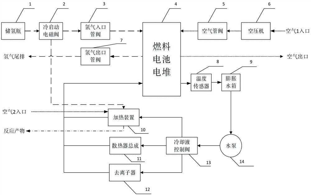
[0031] figure 1 Shown is a basic embodiment of the present invention, a system structure diagram of a fuel cell engine hydrogen combustion heater, including hydrogen storage through a cold start solenoid valve 2 connected to the hydrogen inlet pipe valve 3 on the proton exchange membrane fuel cell stack 4 The bottle 1 and the air compressor 6 connected to the air pipe valve 5 on the fuel cell stack 4 also include an expansion tank 9 connected to the fuel cell stack 4, a heating device 10, a radiator assembly 11 and a deionizer 12 , the fuel cell stack 4 is also provided with a hydrogen outlet pipe valve 7, a temperature sensor 8 is connected between the expansion tank 9 and the fuel cell stack 4, the expansion tank 9 is connected with a cooling water pump 14, and the cooling water pump 14 is connected to the heating device 10, the radiator assembly 11 and the deionizer 12 through the coolant control valve 13 at the same time.
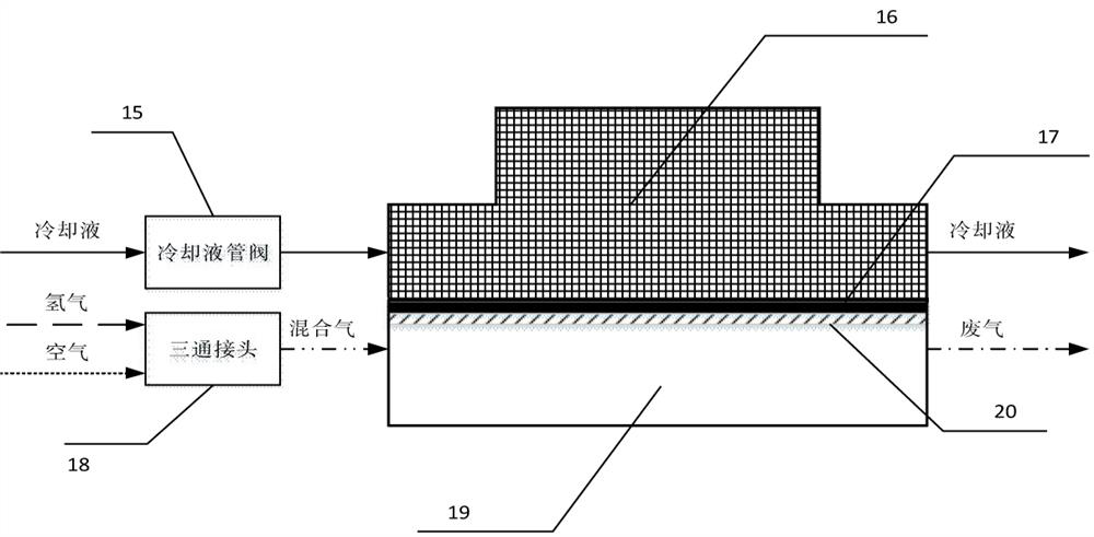
[0032] figure 2 It is a schematic diagram of t...
Embodiment 2
[0040] In the method for realizing self-starting at extremely low temperatures, step (2) is ahead of step (1) by a specific time. Moreover, the solenoid valve 2 opens when the ambient temperature is -8°C to -3°C, which can be -7°C or -5°C. The reason is that after the temperature rises to the critical temperature of -3°C, it can operate normally and is lower than -3°C. You must press a special operation to succeed.
Embodiment 3
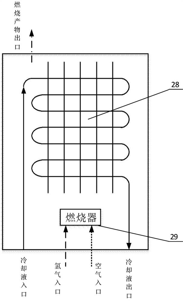
[0042] image 3 It is a schematic diagram of the principle of a heating device 10 according to another embodiment of the present invention, including a heating chamber with a bracket 26 underneath and a cooling device arranged in the heating chamber. A cooling liquid flow channel 23 is arranged in the cooling device, and the heating chamber A cooling liquid inlet 24 and a cooling liquid outlet 25 connected to the cooling liquid flow channel 23 are arranged on the outside, a mixed gas flow channel 27 is outside the cooling device, and a mixed gas inlet 21 and a mixed gas outlet 22 are respectively arranged on the upper side of the heating chamber.
PUM
 Abstract
Description
Claims
Application Information
 - R&D
- Intellectual Property
- Life Sciences
- Materials
- Tech Scout
- Unparalleled Data Quality
- Higher Quality Content
- 60% Fewer Hallucinations
Browse by: Latest US Patents, China's latest patents, Technical Efficacy Thesaurus, Application Domain, Technology Topic, Popular Technical Reports.
© 2025 PatSnap. All rights reserved.Legal|Privacy policy|Modern Slavery Act Transparency Statement|Sitemap|About US| Contact US: help@patsnap.com


