Bedside fixing device for nursing of blood dialysis room
A fixing device and dialysis room technology, which is applied in the field of nursing, can solve the problems of dialysis tubes being pulled, unable to be rolled up or tied up, and achieve the effect of avoiding cumbersome steps, excellent clamping effect, and quick clamping and removal
- Summary
- Abstract
- Description
- Claims
- Application Information
AI Technical Summary
Problems solved by technology
Method used
Image

Examples
Embodiment 1
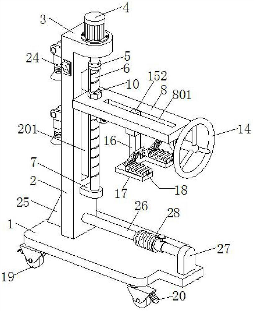
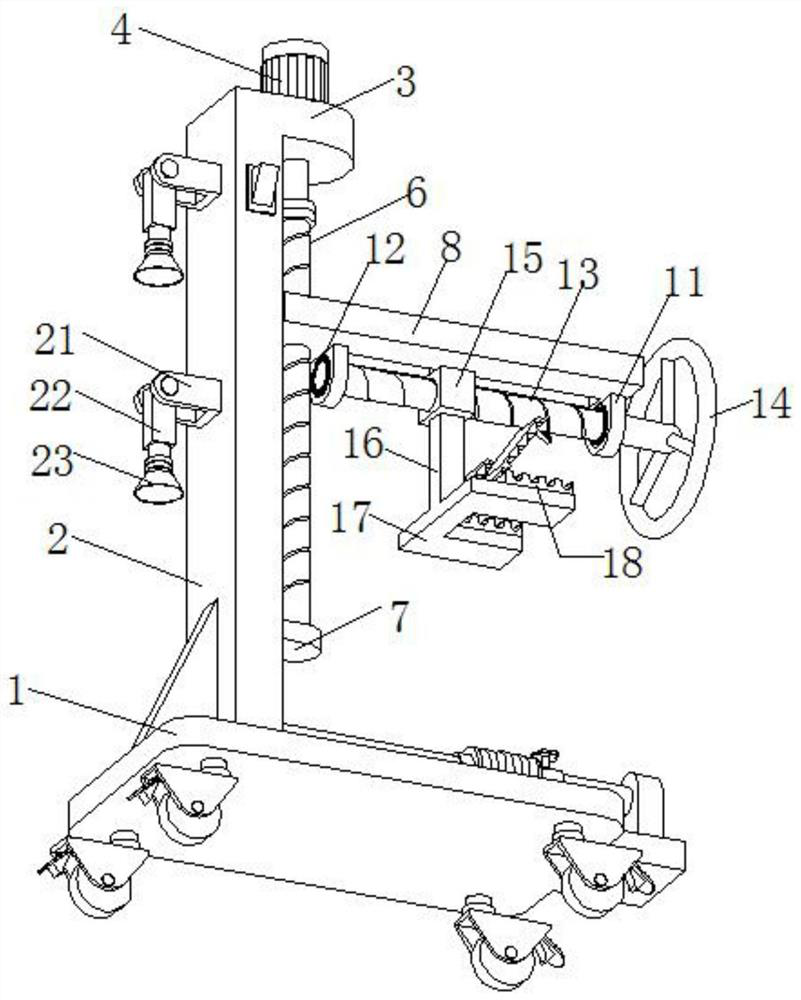
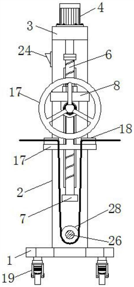
[0032] Example 1 introduces a bedside fixing device for nursing care of a hemodialysis room. Its main structure includes a bottom plate 1. figure 1 And figure 2 A vertical plate 2 is fixedly connected to the upper surface of the bottom plate 1. In order to strengthen the connection stability of the vertical plate 2, a triangular reinforcing rib 25 is also provided at the connection between the rear side of the vertical plate 2 and the bottom plate 1. The front side of the vertical plate 2 is provided with a vertical limit chute 201, the top of the vertical plate 2 is connected with a convex plate 3, and the upper surface of the convex plate 3 is provided with a driving motor 4, of course, the driving motor 4 also includes a power connection terminal ( This embodiment will not be specifically described.) The output shaft of the drive motor 4 passes through the end of the convex plate 3 and is connected to the vertical screw 6 through the coupling 5, which is located in front of ...
Embodiment 2
[0037] Embodiment 2 is a further improvement made on the basis of embodiment 1, which will be described in detail below:
[0038] Example 2 introduces a bedside fixing device for nursing care of a hemodialysis room. Its main structure includes a bottom plate 1. figure 1 And figure 2 , The four corners of the lower surface of the bottom plate 1 are provided with universal wheels 19 and brake foot brakes 20 are provided on the universal wheels 19. A vertical plate 2 is fixedly connected to the upper surface of the bottom plate 1. In order to strengthen the connection stability of the vertical plate 2, a triangular reinforcing rib 25 is also provided at the connection between the rear side of the vertical plate 2 and the bottom plate 1. The front side of the vertical plate 2 is provided with a vertical limit chute 201, the top of the vertical plate 2 is connected with a convex plate 3, and the upper surface of the convex plate 3 is provided with a driving motor 4, of course, the dr...
Embodiment 3
[0044] Embodiment 3 is a further improvement made on the basis of embodiment 2, which will be described in detail below:
[0045] Example 3 introduces a bedside fixing device for nursing care of a hemodialysis room. Its main structure includes a bottom plate 1. figure 1 And figure 2 , The four corners of the bottom surface of the bottom plate 1 are provided with universal wheels 19, and brake foot brakes 20 are provided on the universal wheels 19. A vertical plate 2 is fixedly connected to the upper surface of the bottom plate 1. In order to strengthen the connection stability of the vertical plate 2, a triangular reinforcing rib 25 is also provided at the connection between the rear side of the vertical plate 2 and the bottom plate 1. The front side of the vertical plate 2 is provided with a vertical limit chute 201, the top of the vertical plate 2 is connected with a convex plate 3, and the upper surface of the convex plate 3 is provided with a driving motor 4, of course, the ...
PUM
 Abstract
Description
Claims
Application Information
 - R&D
- Intellectual Property
- Life Sciences
- Materials
- Tech Scout
- Unparalleled Data Quality
- Higher Quality Content
- 60% Fewer Hallucinations
Browse by: Latest US Patents, China's latest patents, Technical Efficacy Thesaurus, Application Domain, Technology Topic, Popular Technical Reports.
© 2025 PatSnap. All rights reserved.Legal|Privacy policy|Modern Slavery Act Transparency Statement|Sitemap|About US| Contact US: help@patsnap.com