Cleaning device for agricultural machine parts

A technology of cleaning device and agricultural machinery, which is applied in the direction of cleaning method using liquid, dryer, drying gas arrangement, etc., can solve the problems of inability to dry agricultural machinery parts, unsatisfactory cleaning effect, and reducing the practicability of cleaning device, etc. To achieve the effect of improving uniform drying effect and uniform hot air

Pending Publication Date: 2020-10-02
HUNAN AGRICULTURAL UNIV
View PDF1 Cites 3 Cited by
  • Summary
  • Abstract
  • Description
  • Claims
  • Application Information

AI Technical Summary

Problems solved by technology

However, when the above technical solution is in use, not only the cleaning effect is not ideal, but also the cleaned agricultural machinery parts cannot be dried, which reduces the practicability of the cleaning device

Method used


Image

  • Cleaning device for agricultural machine parts
  • Cleaning device for agricultural machine parts
  • Cleaning device for agricultural machine parts

Examples


Embodiment 1

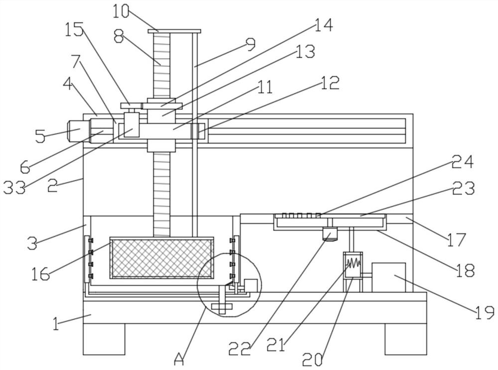
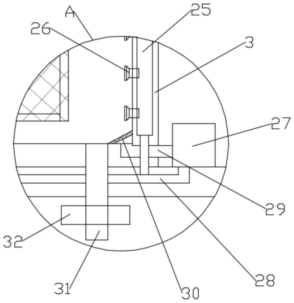
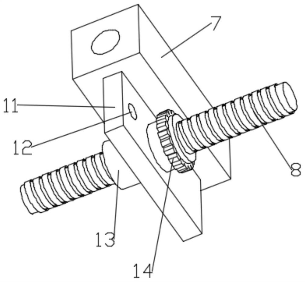
[0025] Such as Figure 1-3 As shown, in the embodiment provided by the present invention, a cleaning device for agricultural machinery parts includes a support base 1, and a support back plate 2 is fixedly arranged on the rear upper surface of the support base 1, and the support back plate 2 The top of the top is fixedly provided with a cleaning box 3, a supporting top seat 4, and an adjusting screw rod 6 is rotated on the supporting top seat 4, and the adjusting slider 7 arranged on the supporting top seat 4 is slid horizontally through a threaded connection. Located on the adjusting screw 6, one end of the supporting top seat 4 is also equipped with a first forward and reverse servo motor 5 for driving the adjusting screw 6 to rotate. Therefore, the embodiment of the present invention utilizes the first positive and negative The reverse servo motor 5 drives the adjustment screw mandrel 6 to rotate, and then the horizontal position of the adjustment slider 7 on the support to...

Embodiment 2

[0030] Such as Figure 1-3 As shown, in the embodiment provided by the present invention, a cleaning device for agricultural machinery parts includes a support base 1, and a support back plate 2 is fixedly arranged on the rear upper surface of the support base 1, and the support back plate 2 The top of the top is fixedly provided with a cleaning box 3, a supporting top seat 4, and an adjusting screw rod 6 is rotated on the supporting top seat 4, and the adjusting slider 7 arranged on the supporting top seat 4 is slid horizontally through a threaded connection. Located on the adjusting screw 6, one end of the supporting top seat 4 is also equipped with a first forward and reverse servo motor 5 for driving the adjusting screw 6 to rotate. Therefore, the embodiment of the present invention utilizes the first positive and negative The reverse servo motor 5 drives the adjustment screw mandrel 6 to rotate, and then the horizontal position of the adjustment slider 7 on the support to...


PUM


Abstract

The embodiment of the invention relates to the field of agricultural equipment, and particularly discloses a cleaning device for agricultural machine parts. The cleaning device comprises a supportingbase and a supporting top seat, wherein a supporting back plate is fixedly arranged on the upper surface of the rear side of the supporting base, a cleaning box is fixedly arranged at the top end of the supporting back plate, an adjusting lead screw is rotationally arranged on the supporting top seat, and an adjusting sliding block horizontally arranged on the supporting top seat in a sliding modeis arranged on the adjusting lead screw in a threaded connection and sleeving mode. According to the cleaning device, the height position of a net cage is adjusted through an arranged height adjusting assembly, so that the net cage extends into the cleaning box, then a liquid spraying assembly is used for spraying cleaning liquid to the net cage, and then the effect of cleaning parts in the net cage is achieved; and after cleaning, the net cage is suspended above a supporting platform by adjusting the horizontal position of an adjusting sliding block, and then the parts in the net cage suspended above the supporting platform are blown and dried through an air blowing assembly.

Description

technical field [0001] The invention relates to the field of agricultural equipment, in particular to a cleaning device for agricultural machinery parts. Background technique [0002] Agricultural machinery refers to various machinery used in the process of crop planting and animal husbandry production, as well as in the process of primary processing and handling of agricultural and animal products. Agricultural machinery includes agricultural power machinery, farmland construction machinery, soil tillage machinery, planting and Fertilization machinery, plant protection machinery, farmland drainage and irrigation machinery, crop harvesting machinery, agricultural product processing machinery, animal husbandry machinery and agricultural transportation machinery, etc. [0003] When cleaning agricultural machinery parts, it is necessary to use a cleaning device for cleaning. In the Chinese patent with the authorized announcement number CN210112944U, a cleaning device for agricu...

Claims


Application Information

Patent Timeline
Patent Type & Authority Applications(China)
IPC IPC(8): B08B3/02B08B13/00F26B21/00
CPCB08B3/02B08B13/00F26B21/001F26B21/004
Inventor 吴志立张乐杨扬吴明亮
Owner HUNAN AGRICULTURAL UNIV
Why Eureka
Try Eureka