
Liquid storage barrel for optical grinding and polishing machine

A technology for optical grinding and polishing machines, which is applied to optical surface grinding machines, grinding/polishing equipment, and parts of grinding machine tools. Grinding, good filtering effect, avoiding the effect of precipitation

Pending Publication Date: 2020-10-02
四川炬科光学科技有限公司 +1
View PDF0 Cites 2 Cited by
  • Summary
  • Abstract
  • Description
  • Claims
  • Application Information

AI Technical Summary

Problems solved by technology

[0004] 1. The water pump is used for stirring, and the water pump is prone to fall. When the machine is shut down, the polishing liquid will all flow back into the storage liquid bucket, causing the polishing liquid to overflow, causing the water pump to immerse, and causing safety accidents;
[0005] 2. In the process of processing, it is easy to produce impurities, which will affect the quality of the lens

Method used


Image

  • Liquid storage barrel for optical grinding and polishing machine
  • Liquid storage barrel for optical grinding and polishing machine
  • Liquid storage barrel for optical grinding and polishing machine

Examples


Embodiment 1

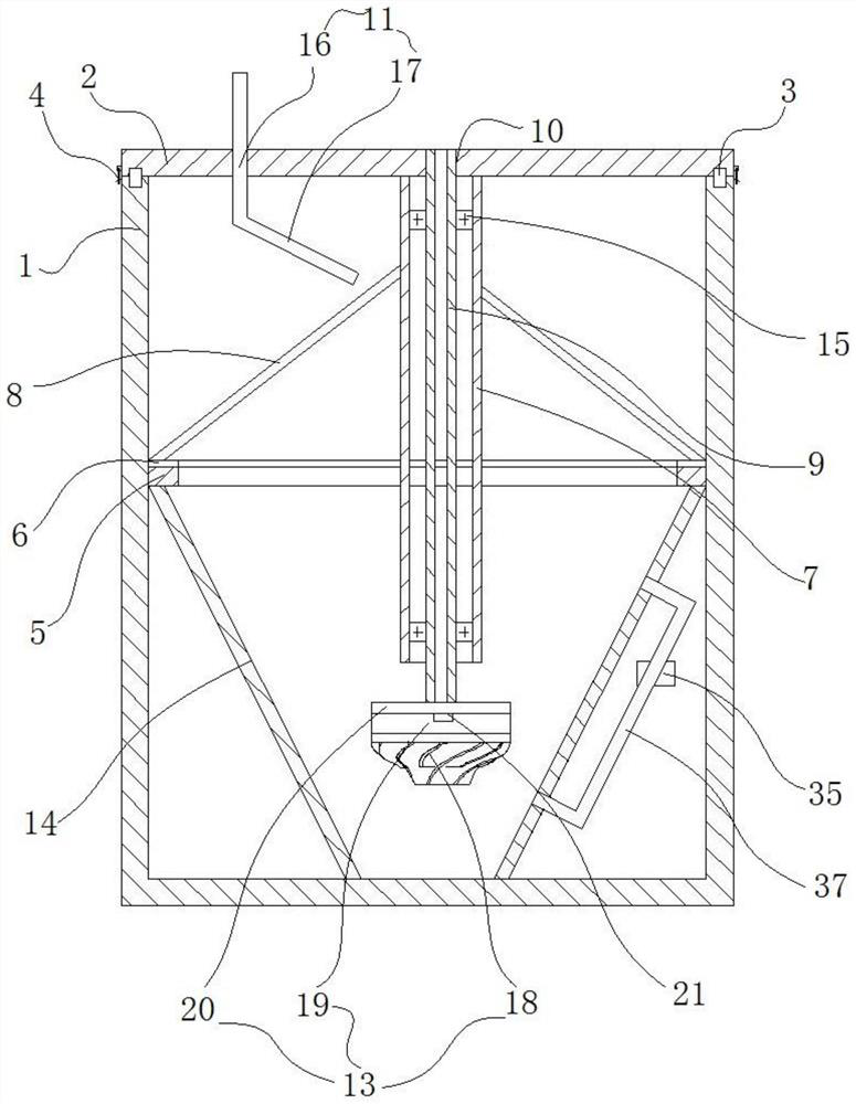
[0030] This embodiment discloses a liquid storage barrel for an optical grinding and polishing machine. 1 Realize detachable connection;

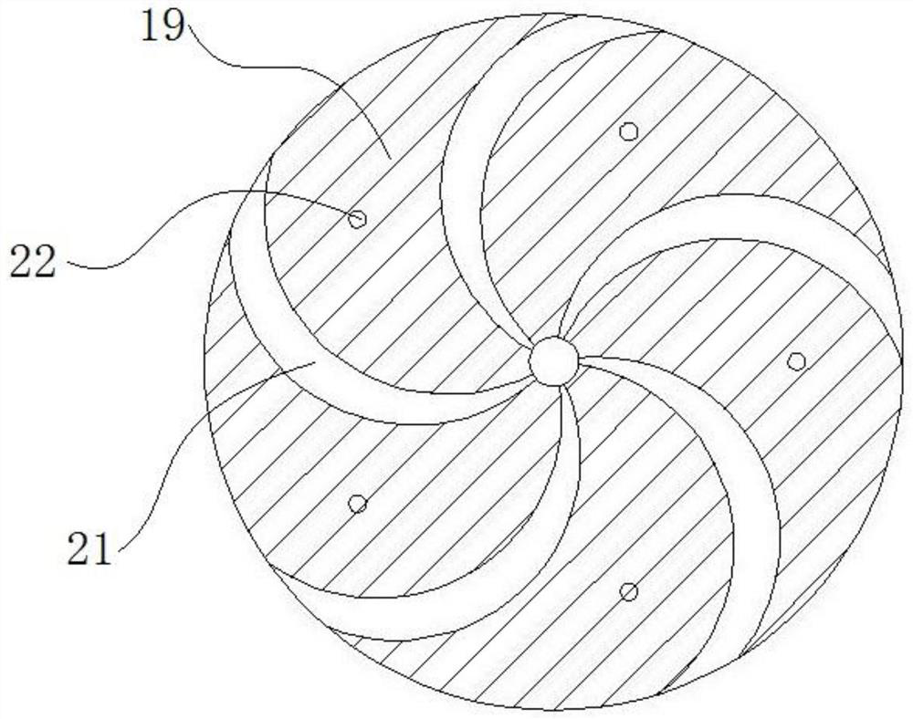
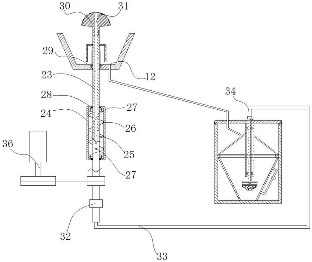
[0031] A boss 5 is arranged in the middle of the barrel body 1, a first sealing strip 6 is arranged on the boss 5, a rotating shaft jacket 7 is connected to the barrel cover 2, and a filter plate 8 in an umbrella-shaped structure is arranged on the outside of the rotating shaft jacket 7 , the filter plate 8 is provided with a spiral step, and the filter plate 8 is provided with a micro-filter hole; a hollow rotary rod 9 is provided through a bearing 15 in the rotary shaft outer cover 7, a liquid outlet 10 is provided on the barrel cover 2, and a hollow rotary rod 9 The bung 2 can be stretched out from the outlet hole 10, and a return pipe 11 is also arranged on the bung 2, and the return pipe 11 is used to be connected with the polishing fluid return passage 12 of the polishing machine; Suction device connection;

[0032] An impeller asse...

Embodiment 2

[0048] This embodiment is further optimized on the basis of Embodiment 1. In this embodiment, a liquid level detection device 35 is provided on the bucket body 1, and the liquid level detection device 35 is connected with an alarm.

[0049] It is further defined that the liquid level detection device 35 is a liquid level detection sensor; in this way, it can give an alarm in time when the polishing liquid is lower than the preset liquid level line, so as to avoid dry grinding due to insufficient polishing liquid.

[0050] In this embodiment, the liquid level detection sensor includes a light source generator and a light source receiver, and a communication pipe 37 is arranged on the side wall of the water guide cylinder 14. The light source generator and light source receiver are arranged on the communication pipe 37, and the light source generator emits ultraviolet light. light, when there is polishing liquid in the connecting pipe 37, the ultraviolet light cannot pass through...


PUM


Abstract

The invention discloses a liquid storage barrel for an optical grinding and polishing machine. The liquid storage barrel comprises a barrel body and a barrel cover, wherein a sealing strip is arrangedbetween the barrel cover and the barrel cover, and the barrel cover is detachably connected with the barrel body through a buckle; a boss is arranged in the middle of the barrel body, a first sealingstrip is arranged on the boss, a rotating shaft outer sleeve is connected to the barrel cover, a filter plate of an umbrella-shaped structure is arranged on the outer side of the rotating shaft outersleeve, a spiral step is arranged on the filter plate, and micro filter holes are formed in the filter plate; a hollow rotating rod is arranged in the rotating shaft outer sleeve through a bearing, aliquid outlet hole is formed in the barrel cover, the hollow rotating rod can extend out of the barrel cover from the liquid outlet hole, a return pipe is further arranged on the barrel cover, and the return pipe is used for being connected with a polishing liquid return channel of the polishing machine; and the liquid outlet hole is used for being connected with a liquid suction device on the polishing machine. The liquid storage barrel has good sealing performance, can prevent external impurities from entering polishing liquid, has a good filtering effect, ensures the quality of a machinedlens, and has the advantage of energy conservation.

Description

technical field [0001] The invention relates to the technical field of optical lens production equipment, in particular to a liquid storage barrel for an optical grinding and polishing machine. Background technique [0002] In the production and processing of optical lenses, a polishing machine is generally used to polish optical lenses, and a polishing liquid is required during the polishing process; in the process of stirring, the stirring blade is generally directly connected to the lower end of the water pump, and the polishing liquid is Stir. [0003] In the prior art, the external liquid supply method is generally adopted, that is, the polishing liquid is rushed to the mold and the optical lens through the provided water pump. The liquid storage tank in the prior art has the following disadvantages: [0004] 1. The water pump is used for stirring, and the water pump is prone to fall. When the machine is shut down, the polishing liquid will all flow back into the stora...

Claims


Application Information

Patent Timeline
Patent Type & Authority Applications(China)
IPC IPC(8): B24B57/02B24B57/00B24B49/10B24B13/00B01D29/03B01F7/26B01F15/00B01F27/93
CPCB24B57/02B24B57/00B24B49/10B24B13/00B01D29/03B01F27/93B01F35/32015
Inventor 黄弢黄立新
Owner 四川炬科光学科技有限公司
Learn More