Clamping jaw mechanism of mechanical arm

A technology of mechanical arms and grippers, which is applied in the field of workpiece transportation, can solve the problems of increased processing costs, reduced service life of flanges, and low efficiency of gripper mechanisms, and achieves the effect of improving use efficiency

Inactive Publication Date: 2020-10-02
JIANGMEN YINXING ROBOTICS LTD
View PDF8 Cites 3 Cited by
  • Summary
  • Abstract
  • Description
  • Claims
  • Application Information

AI Technical Summary

Problems solved by technology

[0004] (1) The gripper mechanism of the traditional robotic arm can only fasten and fix flanges of one size, resulting in low efficiency of the gripper mechanism. At the same time, when it is necessary to transport and position flanges of different sizes When, the processing cost is increased
[0005] (2) The flange is generally positioned and installed manually. When the material of the flange is special, it is very easy to be damaged, which will reduce the service life of the flange.

Method used


Image

  • Clamping jaw mechanism of mechanical arm
  • Clamping jaw mechanism of mechanical arm
  • Clamping jaw mechanism of mechanical arm

Examples


Embodiment Construction

[0030] In order to make the technical means realized by the present invention, creative features, goals and effects easy to understand, the following combination Figure 1 to Figure 6 , to further elaborate the present invention.

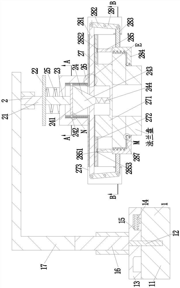
[0031] A gripper mechanism of a mechanical arm, comprising a fixing device 1 and a gripping device 2, the lower end of the fixing device 1 is equipped with a gripping device 2; wherein:

[0032] Described fixture 1 comprises fixed plate 11, rotating column 12, rotating plate 13, motor 14, bevel gear 15, telescopic support 16 and inverted L-shaped plate 17, fixed plate 11 upper end is fixedly installed with rotating column 12, rotates The column 12 is connected with a rotating plate 13 in a sliding fit, the upper end of the fixed plate 11 on the right side is fixed with a motor 14 through a motor 14 seat, the output shaft at the left end of the motor 14 is fixed with a bevel gear 15 through a coupling, and the rotating plate 13 The lower end is prov...


PUM


Abstract

The invention relates to a clamping jaw mechanism of a mechanical arm. The clamping jaw mechanism of the mechanical arm comprises a fixing device and a clamping jaw device; the clamping jaw device isinstalled at the lower end of the fixing device; the fixing device comprises a fixing plate, a rotating column, a rotating plate, a motor, a bevel gear, a first telescopic support and an inverted-L-shaped plate; the clamping jaw device comprises a second telescopic support, a supporting plate, a push column, a circular truncated cone frame, a cylindrical spring, a positioning column, a disc frameand a clamping frame; and the clamping frame comprises a long sliding rod, a rotating rod, a control rod, an arc-shaped block, a guide frame, a small ball and a thick rubber plate. According to the clamping jaw mechanism of the mechanical arm, the clamping jaw device is positioned through the fixing device, meanwhile, horizontal displacement of the clamping jaw device is controlled, flange platesof different sizes are clamped and fixed through the clamping jaw device, the clamping jaw device can be controlled to clamp the flange plates only through the second telescopic support, and thereforethe use efficiency of equipment is improved.

Description

technical field [0001] The invention relates to the field of workpiece transportation, in particular to a claw mechanism of a mechanical arm. Background technique [0002] The clamping mechanism is a mechanism for clamping and fixing workpieces and various objects. The transportation of objects cannot be separated from the clamping mechanism. The hole used is used to connect other things, because it is widely used in machinery, so it needs to be transported after the production is completed. In order to reduce the damage of the flange during transportation, the flange is clamped by the clamp mechanism. Clamp and secure,. [0003] In the process of clamping and fixing the flange, due to the structural limitations of the flange, the following problems exist in the actual operation process: [0004] (1) The gripper mechanism of the traditional robotic arm can only fasten and fix flanges of one size, resulting in low efficiency of the gripper mechanism. At the same time, when ...

Claims


Application Information

Patent Timeline
IPC IPC(8): B25J15/00B65G47/90
CPCB25J15/00B65G47/90
Inventor 陈荣斌林安江
Owner JIANGMEN YINXING ROBOTICS LTD
Why Eureka
Try Eureka