Bagging system for sponge inner sleeve

A sponge and bagging technology, applied in the direction of external support, transportation packaging, packaging, etc., can solve the problems of stacking and storing multiple sponges, sticking sponges together, troubles, etc.

Pending Publication Date: 2020-10-02
南通恒康数控机械股份有限公司
View PDF0 Cites 1 Cited by
  • Summary
  • Abstract
  • Description
  • Claims
  • Application Information

AI Technical Summary

Problems solved by technology

[0005] At present, in the existing sponge production process, when the finished sponge is stored, packaged, transported, etc., due to the limitation of the material of the sponge itself, it is inevitable that the sponge itself will have a certain degree of stickiness, so it is not possible to directly use multiple The sponges are stacked and stored, otherwise the long-term contact will easily cause the adjacent sponges to stick together. In the follow-up operation, the sponges need to be separated, which is more troublesome and easy to cause damage to the sponges. Therefore, in view of the above phenomenon, A gauze bag will be put on the outside of the sponge as the inner sleeve of the sponge to avoid the above phenomenon. At present, the traditional bagging method is manually bagged, and the size of the existing gauze bag is not The size of the sponge is matched one by one, but the yarn bobbin about tens of meters long is cut, stitched and other operations to achieve the size that matches the size of the sponge. The above-mentioned processes are all manually operated. , the whole bagging process needs to consume a lot of manual labor, the labor intensity is high, and the work efficiency is not high

Method used


Image

  • Bagging system for sponge inner sleeve
  • Bagging system for sponge inner sleeve
  • Bagging system for sponge inner sleeve

Examples


Embodiment Construction

[0083] The following examples can enable those skilled in the art to understand the present invention more comprehensively, but the present invention is not limited to the scope of the described examples.

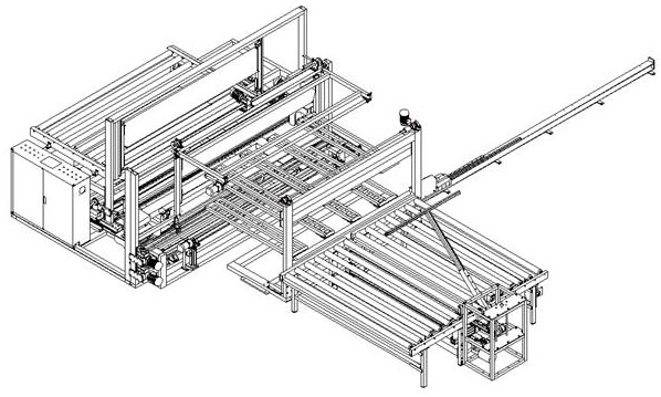
[0084] Such as Figure 1-Figure 20 A bagging system for inner sponge is shown, which includes a feeding unit, a bagging unit, a cutting and overlocking unit, and a discharging unit arranged in sequence.

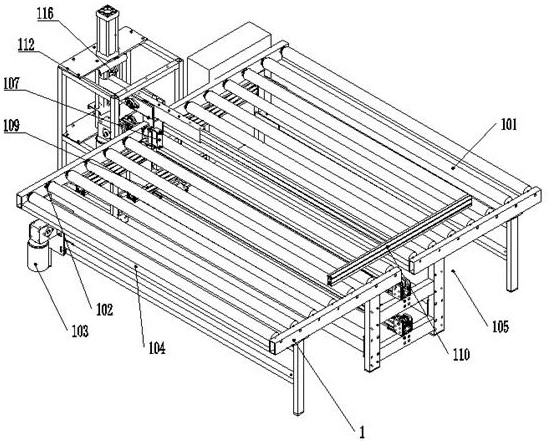
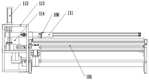
[0085] Such as Figure 2-Figure 6 As can be seen from the schematic diagram shown, the feeding unit includes

[0086] A feeding bracket 1, on which a number of conveying rollers 101 are installed, the two sides of the conveying rollers 101 roll and cooperate with the feeding bracket 1 through the rotating shaft, and each conveying roller 101 is installed on the rotating shaft on the same side There are interlocking sprockets 102, and each interlocking sprocket 102 realizes linkage through interlocking chain connection, wherein any interlocking sprocket 102 is driven by t...


PUM


Abstract

The invention relates to a bagging system for a sponge inner sleeve. The bagging system comprises a feeding unit, a bagging unit, a cutting and overseam unit and a discharging unit sequentially arranged. The bagging system has the following advantages: through mutual cooperation of the feeding unit, the bagging unit, the cutting and overseam unit and the discharging unit, automatic conveying and bagging of sponge and automatic cutting and overseam unit of a yarn bag are realized, manual labor is greatly reduced during the entire process, effectively saves the labor force and correspondingly improves the working efficiency.

Description

technical field [0001] The invention relates to the field of sponge processing, in particular to a bagging system for a sponge inner sheath. Background technique [0002] Polyurethane soft foam rubber. Polyurethane is the most common polymer material in life. It is widely used in the production of various sponge products, as well as elastic materials for shock absorption and anti-friction purposes, such as shoe soles and tractor tank track substrates. [0003] When the sponge product is processed, first, the foaming resin, foaming aid and binder resin (to make the finished product have adhesiveness) are mixed together; then the foaming process is carried out. Mix ethylene vinyl acetate (EVA), APAOPT3385, azodicarbonamide, CaCO and dicumyl peroxide together, place it in a mold for foaming, and use mechanical force to break the closed cells to make a foamed sponge The product has a density (d) of 0.028g / cm and a 25% compression hardness of 1.9KPa. [0004] The composition of...

Claims


Application Information

Patent Timeline
Patent Type & Authority Applications(China)
IPC IPC(8): B65B35/42B65B35/40B65B35/56B65B51/07B65B61/06
CPCB65B35/40B65B35/42B65B35/56B65B51/07B65B61/06
Inventor 倪张根袁海峰吴晓宇林长彬王力姜清青张陈波
Owner 南通恒康数控机械股份有限公司
Why Eureka
Try Eureka