Pressure control sliding sleeve

A technology of pressure control and sliding sleeve, which is applied in the direction of wellbore/well components, earthwork drilling, sealing/isolation, etc., and can solve problems such as breakage, difficult operation and high operation cost

Pending Publication Date: 2020-10-02
深圳百途石油技术服务有限公司
View PDF0 Cites 0 Cited by
  • Summary
  • Abstract
  • Description
  • Claims
  • Application Information

AI Technical Summary

Problems solved by technology

[0004] As a result, at least two slickline operations are required for well completion, and at least one slickline operation is required for well workover, but slickline operations have many shortcomings: long operation time, high operation costs, and hidden dangers such as knotting, falling, easy to get hooked
In addition, in incli...

Method used


Image

  • Pressure control sliding sleeve
  • Pressure control sliding sleeve
  • Pressure control sliding sleeve

Examples


Embodiment 1

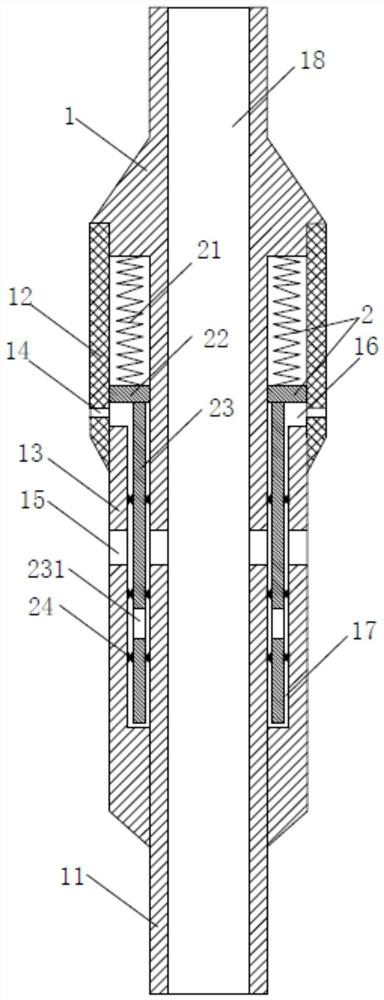
[0020] This embodiment relates to a pressure control sliding sleeve, such as figure 1 As shown, it includes: sliding sleeve body 1 and hydraulic control switch 2. Wherein, the sliding sleeve body 1 is provided with a hydraulic hole 14 and a liquid inlet hole 15 . The hydraulic hole 14 communicates with the annular space 3 and the hydraulic control switch 2 , and the liquid inlet hole 15 communicates with the annular space 3 , the inner cavity of the sliding sleeve body 1 and the hydraulic control switch 2 . The hydraulic control switch 2 is movably assembled in the sliding sleeve body 1, and the hydraulic control switch 2 is used to open or close the liquid inlet hole 15 according to the change of the external hydraulic pressure. By controlling the pressure in the annular space 3 to control the opening or closing of the sliding sleeve, it not only saves operation time and cost, thereby reducing the time and cost of oil field development, but also reduces the difficulty of ope...

Embodiment 2

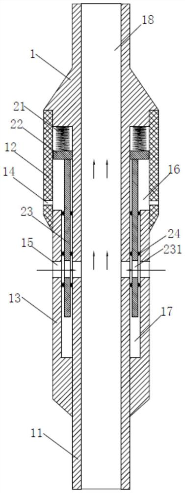
[0026] The main difference between this embodiment and Embodiment 1 is that the sliding sleeve body 1 includes: an inner shell 11 and an upper shell 12 , the upper shell 12 is partly sleeved outside the inner shell 11 , and one end thereof is fixedly assembled on the inner shell 11 . The cavity 16 is disposed between the inner shell 11 and the upper shell 12 . The hydraulic hole 14 is arranged on the upper shell 12 , the liquid inlet hole 15 is arranged on the inner shell 11 , and both the hydraulic hole 14 and the liquid inlet hole 15 communicate with the cavity 16 .

[0027] The hydraulic control switch 2 includes: an elastic member 21 and a piston 22 . The elastic member 21 is assembled in the cavity 16 . The piston 22 is movably assembled in the cavity 16 , located between the hydraulic hole 14 and the liquid inlet hole 15 , and one end thereof abuts against the elastic member 21 . The piston 22 reciprocates linearly in the cavity 16 under the action of the external hydr...


PUM


Abstract

The invention provides a pressure control sliding sleeve, and relates to the technical field of well completion operation. The pressure control sliding sleeve comprises a sliding sleeve body and a hydraulic control switch, wherein a hydraulic hole and a liquid inlet hole which communicate with an annulus are formed in the sliding sleeve body; and the hydraulic control switch is movably assembled in the sliding sleeve body, communicates with the hydraulic hole and is used for opening or closing the liquid inlet hole according to change of external hydraulic pressure. A cavity and a subspace which communicate with the hydraulic hole and the liquid inlet hole and are used for assembling the hydraulic control switch are arranged in the sliding sleeve body, and the hydraulic control switch comprises an elastic piece assembled in the cavity, a piston which is movably assembled in the cavity and does linear reciprocating motion in the cavity under the action of the external hydraulic pressureand the elastic piece, and a piston gate plate which is movably assembled in the subspace, is fixedly connected with the piston and is used for moving along with the piston to open or close the liquid inlet hole. By the technical scheme, the pressure control sliding sleeve has the advantages that the operation time is saved, the operation cost is reduced, the operation difficulty is reduced, andthe operation hidden danger of steel wire operation is eliminated.

Description

technical field [0001] The invention relates to the technical field of well completion operations, in particular to a pressure control sliding sleeve. Background technique [0002] In traditional well completion operations, in order to protect the casing, the fluid in the annulus must be replaced with corrosion-resistant completion fluid after the packer is set. At this time, steel wire operation is required, that is, the sliding sleeve is opened by using the steel wire belt sliding sleeve switch tool, and then the completion fluid is circulated into the annulus. After replacing the completion fluid, the sliding sleeve is closed through steel wire operation to ensure the integrity of the tubing. [0003] Also in the workover of oil and gas wells, for operational safety, before the well completion tool and the oil pipe are taken out from the well, it is also necessary to send the sliding sleeve switch tool into the oil pipe through steel wire operation to open the sliding sl...

Claims


Application Information

Patent Timeline
IPC IPC(8): E21B34/08
CPCE21B34/08
Inventor 沈夺为
Owner 深圳百途石油技术服务有限公司
Why Eureka
Try Eureka