Slotting type wind turbine blade device and slotting method thereof

A technology of wind turbine blades and blade bodies, which is applied in the direction of wind engines, wind engines, and wind engine control in the same direction as the wind. Pressure, the effect of increasing the positive pressure surface pressure

Active Publication Date: 2020-10-02
中国华能集团有限公司广西分公司 +1
View PDF19 Cites 2 Cited by
  • Summary
  • Abstract
  • Description
  • Claims
  • Application Information

AI Technical Summary

Problems solved by technology

Although the vortex generator can effectively control the flow separation on the surface of the blade and improve the performance of the blade, the problem it brings is fatal: this flow control method has a specific design range, and the performance can be improved within the design range, but Under other conditions that do not require flow control, such as a small collective pitch angle and no flow separation on the blade surface, the effect of the vortex generator is negative at this time, causing an increase in drag and a decrease in lift-to-drag ratio

Method used


Image

  • Slotting type wind turbine blade device and slotting method thereof
  • Slotting type wind turbine blade device and slotting method thereof
  • Slotting type wind turbine blade device and slotting method thereof

Examples


Embodiment 1

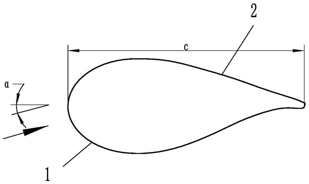
[0042] Such as Figure 6 , Figure 7 and Figure 10 As shown, it is a slotted wind turbine blade device, including a blade body, the blade body includes a positive pressure surface 1 and a back pressure surface 2, and a gap 3 connecting the positive pressure surface 1 and the back pressure surface 2 is provided inside the blade body, After the gas flows into the gap 3 from the positive pressure surface 1, the gas flows out from the back pressure surface 2. The gap 3 includes an air inlet 11 on the positive pressure surface 1 and an air outlet 21 on the back pressure surface 2 , and a surge tank 32 is also provided in the gap 3 . The air inlet 11 and the air outlet 21 are respectively connected to the surge tank 32 through the pipeline 31 , and the tapered surfaces 22 gradually approaching inward are respectively provided between the air inlet 11 and the pipeline 31 and between the air outlet 21 and the pipeline 31 . The tapered surface 22 is a corrugated surface, which can ...

Embodiment 2

[0044] Such as Figure 11 As shown, the difference between Embodiment 2 and Embodiment 1 is that: the air inlet 11 is an intermittent opening, and the different openings are collected into the same pipe 31 through the tapered surface 22 and connected to the surge tank 32 .

Embodiment 3

[0046] Such as Figure 12 As shown, the difference between Embodiment 3 and Embodiment 1 is that: the air inlet 11 is provided with two channels arranged at intervals, and the two air inlets 11 communicate with the surge tank 32 through different pipes 31 respectively.


PUM


Abstract

The invention discloses a slotting type wind turbine blade device and a slotting method thereof. The slotting type wind turbine blade device comprises a blade body; the blade body comprises a positivepressure face and a back pressure face; a gap communicating with the positive pressure face and the back pressure face is formed inside the blade body, the gap comprises a gas inlet located in the positive pressure face and a gas outlet located in the back pressure face, and after gas flows into the gap from the positive pressure face and then flows out from the back pressure face. The slotting method thereof has the beneficial effects that an extra gas source is not needed, an extra device does not need to be additionally arranged on the surface of a fan blade, and flow control is achieved;high-pressure gas on the positive pressure face is introduced into a low-pressure area on the back pressure face, so that the flow velocity of the positive pressure face is reduced, the pressure of the positive pressure face is increased, in addition, the flow velocity of the back pressure face is increased, the pressure of the back pressure face is reduced, and the lift of the blade is further improved. Compared with the mode that a vortex generator is directly installed on the surface of the blade, damage to the surface of the blade is small, extra resistance cannot be brought under the small attack angle, and it is guaranteed that the aerodynamic performance in the non-flow control state is not reduced.

Description

technical field [0001] The invention belongs to the technical field of wind power generation equipment, in particular to a slotted wind power machine blade device. Background technique [0002] Wind energy is a clean, practically inexhaustible source of energy. Wind turbine blade designs are all designed and optimized for the specific wind speeds of the wind farm in which they will be used, meaning that they are very efficient and performant within the rated wind speed range, but degrade rapidly when operating at wind speeds above the rated wind speed range. For variable-pitch fans, when the inflow angle is large, the flow on the surface of the blade is separated, the lift force is reduced, and the resistance is increased, which also causes the performance of the blade to decline. The airfoil of a fan blade is defined as figure 1 As shown, the upper surface is the back pressure surface 2, the lower surface is the positive pressure surface 1, the left side is the leading ed...

Claims


Application Information

Patent Timeline
Patent Type & Authority Applications(China)
IPC IPC(8): F03D1/06F03D7/02
CPCF03D1/0675F03D7/024Y02E10/72
Inventor 李宝山周民强牛凤国周晓亮龚玉祥孙剑
Owner 中国华能集团有限公司广西分公司
Why Eureka
Try Eureka