Method of preventing corrosion of pipe bundles in heat exchanger and at outlet of heat exchanger
A technology for heat exchangers and outlets, which is applied in the direction of damage protection, heat exchange equipment, and cleaning heat transfer devices. Under-deposit corrosion, prevention of dew point corrosion leakage, good detection effect
Pending Publication Date: 2020-10-02
LUOYANG DEMING PETRIFACTION EQUIP
View PDF0 Cites 0 Cited by
- Summary
- Abstract
- Description
- Claims
- Application Information
AI Technical Summary
Problems solved by technology
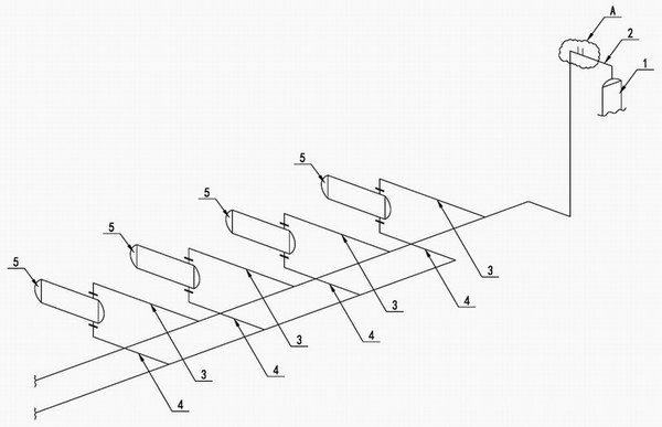
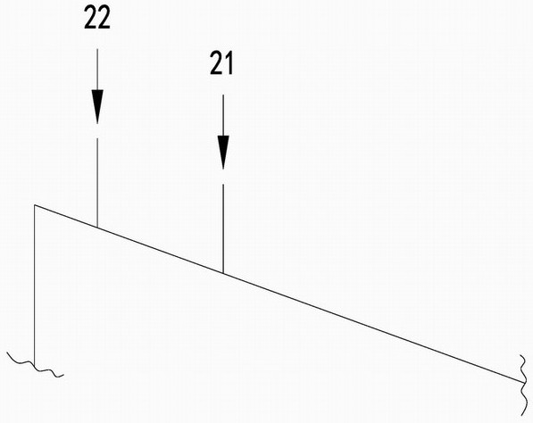
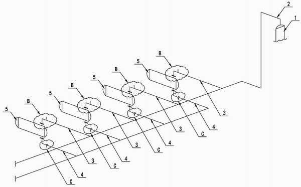
Since the heat exchanger is installed on the multi-way branch pipe downstream of the main pipe, there must be a biased flow phenomenon after the oil and gas enter the multi-way branch pipe from the main pipe. If water and agent are injected into the main pipe, some heat exchangers will be insufficiently watered and injected due to the biased flow. As a result, the problem of corrosion leakage in the internal tube bundle or outlet elbow of the heat exchanger is caused
Method used
View moreImage
Smart ImageViewing Examples
Examples
Embodiment Construction
[0020] The present invention can be explained in more detail by the following examples, but the present invention is not limited to the following examples;
Login to View More PUM
 Abstract
The invention relates to a method of preventing corrosion of pipe bundles in a heat exchanger and at an outlet of the heat exchanger for preventing corrosion and leakage of the pipe bundles in the heat exchanger and at the outlet of the heat exchanger, and belongs to anti-corrosion measures of heat exchangers in petroleum and chemical devices. In particular, water and an agent are injected to an oil and gas pipeline in front of the heat exchangers of multiple branched pipelines.
Description
【Technical field】 [0001] The invention relates to a method for injecting water and neutralizing agent on the oil and gas pipeline at the front inlet of the heat exchanger, which is used to prevent corrosion and leakage of the tube bundle inside and at the outlet of the heat exchanger, and belongs to the oil and chemical equipment. The anti-corrosion measures of the heat exchanger are specifically to inject water and injection agent on the oil and gas pipeline before the heat exchanger of the multi-way branch pipeline. 【Background technique】 [0002] In existing refining and chemical plants, the high-temperature gas phase medium produced by fractionation equipment needs to be cooled and recovered through heat exchangers. For example, in the atmospheric and vacuum unit, the high-temperature oil and gas separated from the crude oil through the fractionation tower needs to be cooled by a heat exchanger, and then recovered in the subsequent unit. However, high temperature oil an...
Claims
Login to View More Application Information
Patent Timeline
 IPC IPC(8): F28F19/00F28G9/00C02F1/66
CPCC02F1/66F28F19/00F28G9/00
Inventor 任宏雷郭向阳
Owner LUOYANG DEMING PETRIFACTION EQUIP
Features
- R&D
- Intellectual Property
- Life Sciences
- Materials
- Tech Scout
- Unparalleled Data Quality
- Higher Quality Content
- 60% Fewer Hallucinations
Learn More Browse by: Latest US Patents, China's latest patents, Technical Efficacy Thesaurus, Application Domain, Technology Topic, Popular Technical Reports.
© 2025 PatSnap. All rights reserved.Legal|Privacy policy|Modern Slavery Act Transparency Statement|Sitemap|About US| Contact US: help@patsnap.com


