A Method for Correcting Misalignment Errors of Large Aperture and Large Field of View Telescopes

An error correction and telescope technology, which is applied in the field of integrated adjustment of telescope systems, can solve problems such as cumbersome implementation process, complex calculation process, and complex algorithm, and achieve the effects of wide application range, simplified measurement system, and reduced algorithm complexity

Active Publication Date: 2022-06-28
INST OF OPTICS & ELECTRONICS - CHINESE ACAD OF SCI
View PDF2 Cites 0 Cited by
  • Summary
  • Abstract
  • Description
  • Claims
  • Application Information

AI Technical Summary

Problems solved by technology

Due to the cumbersome implementation process and complex algorithm, the undersampling image reconstruction technology cannot be directly applied to the online and closed-loop correction process of the telescope misalignment error
At present, the misalignment error correction technology of large aperture and large field of view telescope mainly adopts direct wavefront detection method or image-based wavefront detection method such as phase difference method (Phase Diversity, PD), phase recovery method (Phase Retrieval, PR), etc. , but it is necessary to add a wavefront detection device to the optical system, which increases the complexity of the system, and requires wavefront measurement and reconstruction, resulting in a complicated calculation process

Method used


Image

  • A Method for Correcting Misalignment Errors of Large Aperture and Large Field of View Telescopes
  • A Method for Correcting Misalignment Errors of Large Aperture and Large Field of View Telescopes
  • A Method for Correcting Misalignment Errors of Large Aperture and Large Field of View Telescopes

Examples


example 1

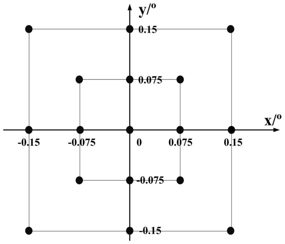
[0037] The RC optical system with a clear aperture of 4m and F#=3 is used for simulation analysis. The system parameters are shown in Table 1. The selected field of view is shown in Table 1. figure 2 shown.

[0038] Table 1 Some parameters of the telescope system

[0039] System parameters Radius Semi-diameter Conic PM -12000 2000 -1.004 SM -2125 330 -1.626

[0040] Taking the central wavelength as 0.55μm, the full width at half maximum of the Airy disk corresponding to the optical system is:

[0041]

[0042] Assuming that the selected detector pixel size is 15μm, take the undersampling factor Q:

[0043]

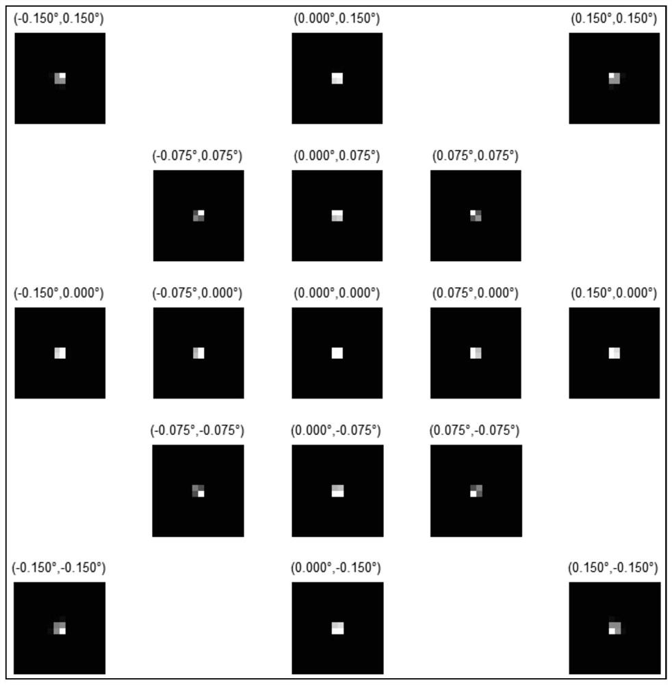
[0044] It can be seen from the above results that the under-sampling magnification of the under-sampling image obtained by the optical system on the detector is a serious under-sampling image because Q=18. The undersampled imaging spot shape in the ideal imaging state of the optical system is as follows: image 3shown. For la...


PUM


Abstract

The invention relates to a method for correcting misalignment errors of a telescope with a large aperture and a large field of view. The imaging spots of each field of view are used for target extraction and field of view matching; (3) Calculate the image definition function of the under-sampled imaging spots of each field of view in the initial misalignment state; (4) Use the optimization algorithm to calculate the new secondary mirror position, and pass The six-degree-of-freedom driver changes the position of the secondary mirror; (5) collects the far-field undersampled imaging spots of each field of view again, and performs target extraction and field of view matching, and calculates the image definition function of each field of view spot; (6) judges and corrects Whether the result satisfies the termination condition, if so, the calibration process ends, otherwise, repeat steps (4)-(6). The present invention can be directly based on the image definition function of far-field under-sampling imaging spot, and can realize the online, closed-loop, high-precision correction process for the misalignment error of large-aperture and large-field-of-view telescopes by using an optimization algorithm.

Description

technical field [0001] The invention relates to the field of integrated installation and adjustment of a telescope system, in particular to a large-diameter and large-field-of-view telescope misalignment error correction method based on a far-field undersampling imaging spot image clarity function. This method is suitable for online tuning of telescope optical systems with undersampled imaging spots. Background technique [0002] In order to detect farther and darker targets, telescope apertures and fields of view have continued to increase. However, during the working process of the telescope, due to the influence of gravity, wind load, vibration, temperature change and other factors, the relative position of each optical mirror surface will change, and the misalignment error will be introduced into the system, making the imaging quality unable to meet the needs of use. At present, the online correction technology of system offset error of large-diameter and large-field te...

Claims


Application Information

Patent Timeline
Patent Type & Authority Patents(China)
IPC IPC(8): G02B27/00G02B23/12G01M11/02
CPCG02B27/0025G02B23/12G01M11/0257
Inventor 鲜浩李敏张昂
Owner INST OF OPTICS & ELECTRONICS - CHINESE ACAD OF SCI
Why Eureka
Try Eureka