Pose compensation device for butting connector and connector assembly

A technology for docking connectors and compensation devices, which is applied in the installation, transportation and packaging of connecting parts, electric vehicles, etc., and can solve problems such as position errors, pulling actuators, damage to connector sockets, etc., and achieve the effect of simple structure

Pending Publication Date: 2020-10-02
SHANGHAI AOWEI TECH DEV
View PDF0 Cites 6 Cited by
  • Summary
  • Abstract
  • Description
  • Claims
  • Application Information

AI Technical Summary

Problems solved by technology

[0003] (1) When inserting the connector into the socket on the receiving box, there will inevitably be a certain position error;
[0004] (2), especially after the charging system starts to charge the batteries of electric vehicles or electric boats, if the body shakes due to passengers getting on and off or the hull fluctuating up and down, because the connector and the charging system are rigidly connected, not only It will pull the actuator connected to the connector, and it will also cause unreliable or invalid connection between the connector and the receiving box, which will affect the charging of the electric vehicle or electric boat, and may also affect the connector and the connector connected to the connector. The actuator and the socket of the receiving box cause damage

Method used


Image

  • Pose compensation device for butting connector and connector assembly
  • Pose compensation device for butting connector and connector assembly
  • Pose compensation device for butting connector and connector assembly

Examples


Embodiment 1

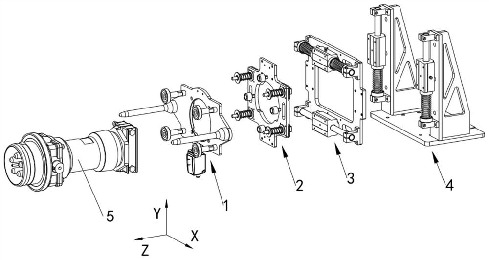
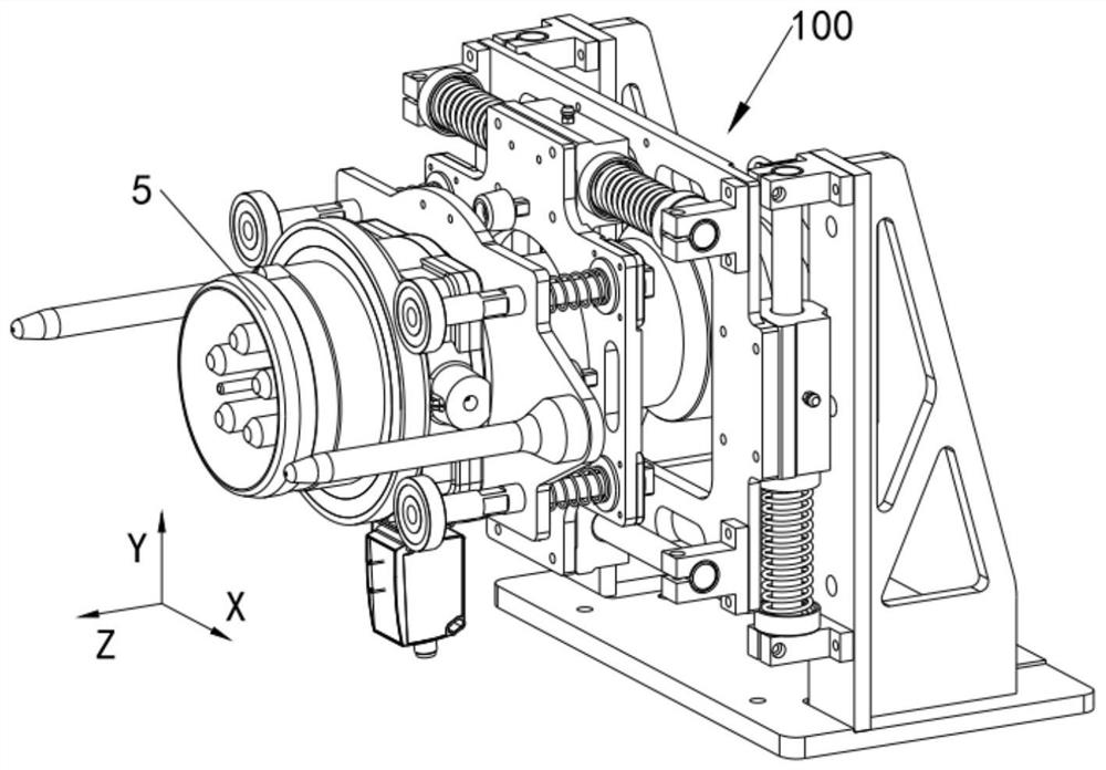
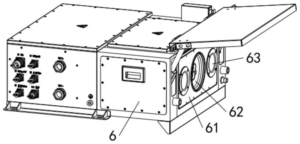
[0062] Such as Figure 1 to Figure 3 As shown, the present embodiment provides a pose compensation device for docking connectors and a connector assembly, the connector assembly includes a connector 5 and a pose compensation device 100 for docking the connector 5 . The above pose compensation device can be applied to the docking of the power receiving box 6 of the electric vehicle and the connector 5, and can also be applied to the docking of the power receiving box and the connector 5 of the electric boat. This embodiment is applied to the connection of the automatic charging system The specific structure of the pose compensation device 100 is introduced by taking the connection between the device 5 and the power receiving box 6 of the electric vehicle as an example.

[0063] The above pose compensation device 100 includes a mounting assembly 1 for connecting the connector 5 . Specifically, such as Figure 4 As shown, the mounting assembly 1 includes a mounting panel 11 and...

Embodiment 2

[0093] The difference between the present embodiment and the first embodiment is that the installation panel 11 is provided with piercing holes corresponding to the floating pins 22 one by one. The panels 21 are connected, and the other end passes through the corresponding hole and is connected to the limiting member 26 , and the limiting member 26 is abutted against the side of the installation panel 11 facing away from the first panel 21 by the first elastic return member 24 .

[0094] In other embodiments, the installation panel 11 and the first panel 21 can also be provided with piercing holes corresponding to the floating pins 22 one by one, the diameter of the piercing holes is larger than the outer diameter of the floating pins 22, and one end of the floating pins 22 Through the corresponding hole on the first panel 21 and connected with the first stopper, the other end passes through the corresponding hole on the installation assembly 1 and connected with the second sto...


PUM


Abstract

The invention relates to the field of connectors, and discloses a pose compensation device for butting a connector and a connector assembly. The pose compensation device comprises a mounting assembly,a first panel assembly, a second panel assembly and a base assembly which are sequentially arranged in the Z direction. The pose compensation device provided by the invention is simple in structure;the connector can rotate in the X direction, the Y direction and the Z direction and reciprocate in the Z direction through the first panel assembly. The second panel assembly enables the connector tomove back and forth along the X direction. The connector can move back and forth in the Y direction through the base assembly, so that the connector is in floating connection with a structure in buttjoint with the connector, six-degree-of-freedom omnibearing compensation of the connector is achieved, the connector cannot bear large pulling force, and the connector and the structure in butt jointwith the connector are protected. The invention further provides the connector assembly which comprises the connector and the pose compensation device used for butting the connector, and the connector is connected to the installation assembly.

Description

technical field [0001] The invention relates to the field of connectors, in particular to a posture compensation device and a connector assembly for docking connectors. Background technique [0002] When charging electric vehicles or electric boats, it is necessary to rigidly connect the charging system, such as the connector on the charging pile, to the receiving box on the electric vehicle or electric boat. There are following technical problems in adopting the above-mentioned docking method: [0003] (1) When inserting the connector into the socket on the receiving box, there will inevitably be a certain position error; [0004] (2), especially after the charging system starts to charge the batteries of electric vehicles or electric boats, if the body shakes due to passengers getting on and off or the hull fluctuating up and down, because the connector and the charging system are rigidly connected, not only It will pull the actuator connected to the connector, and it wi...

Claims


Application Information

Patent Timeline
Patent Type & Authority Applications(China)
IPC IPC(8): H01R13/73B60L53/16
CPCH01R13/73B60L53/16Y02T10/70Y02T10/7072Y02T90/14
Inventor 解凌峰郭天皓龚正大章锦严嵘华黎陈晓林姜琦
Owner SHANGHAI AOWEI TECH DEV
Why Eureka
Try Eureka