
Unmanned aerial vehicle image acquisition method

A technology of image acquisition and UAV, which is applied in the field of UAV, can solve the problems of low image definition and low precision of UAV image acquisition system, and achieve the effect of improving accuracy and definition and improving precision

Active Publication Date: 2020-10-02
ARMY ENG UNIV OF PLA
View PDF7 Cites 3 Cited by
  • Summary
  • Abstract
  • Description
  • Claims
  • Application Information

AI Technical Summary

Problems solved by technology

[0004] Therefore, the technical problem to be solved by the embodiments of the present invention is that the UAV image acquisition system in the prior art has low precision and low image clarity.

Method used


Image

  • Unmanned aerial vehicle image acquisition method
  • Unmanned aerial vehicle image acquisition method
  • Unmanned aerial vehicle image acquisition method

Examples


Embodiment 1

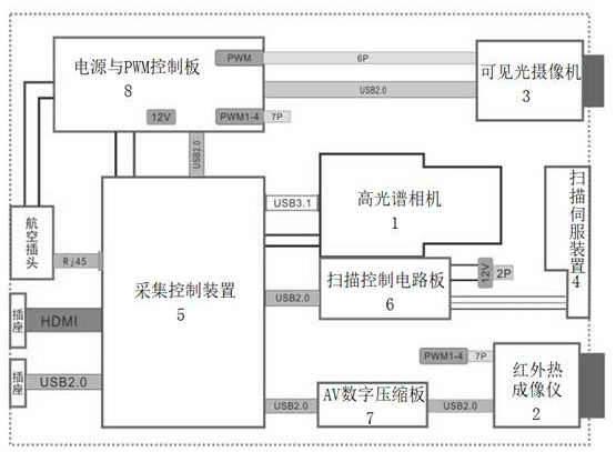
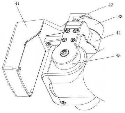
[0046] This embodiment provides a UAV image acquisition system, such as figure 1 and 2 shown, including:

[0047] The hyperspectral camera 1 is connected with the acquisition control device 5, and is used to complete the acquisition of the two-dimensional geometric space and one-dimensional spectral information of the target under the motion of the scanning servo device 4, and the acquisition control device 5 collects the hyperspectral resolution obtained in real time. Continuous, narrow-band image data at a high rate;

[0048] The infrared thermal imager 2 is connected with the acquisition control device 5, and is used to complete the acquisition of the infrared thermal image of the target under the movement of the scanning servo device 4, and the acquisition control device 5 collects the infrared thermal image data obtained in real time;

[0049] The visible light camera 3 is connected with the acquisition control device 5, and is used to complete the acquisition of the vi...

Embodiment 2

[0069] This embodiment provides a UAV image acquisition method, which is applied to the UAV image acquisition system in Embodiment 1. The UAV image acquisition method is stored and executed on the acquisition control device 5, and specifically includes the following steps:

[0070] S1. Judging whether the information including that the drone has flown to the first preset position has been received; according to factors such as the site selection of the shooting task, the hyperspectral camera 1, the infrared thermal imager 2 and the visible light camera 3 and other factors, the first A preset position is selected at a position where the infrared thermal imager 2 and the visible light camera 3 can distinguish the target shape;

[0071] S2. When receiving information that the drone has flown to the first preset position, generate a signal to control the infrared thermal imager 2 or the visible light camera 3 to take photos of a preset size according to the day and night conditions...


PUM


Abstract

The invention discloses an unmanned aerial vehicle image acquisition method, which relates to the technical field of unmanned aerial vehicles and comprises the steps of judging whether information that an unmanned aerial vehicle flies to a first preset position is received or not; generating a signal for controlling an infrared thermal imager or the visible light camera to shoot a picture of a preset size according to the day and night conditions when the signal is received; acquiring image data of the photographed picture with the preset size and acquiring a target outline according to the image data; calculating according to the outline of the target to obtain a geometric center value of the target; judging whether the geometric center value of the target is equal to the geometric centervalue of a shot preset-size picture sent by an infrared thermal imager or a visible light camera or not; if yes, controlling a scanning servo device to move according to the track, and meanwhile controlling a hyperspectral camera or the infrared thermal imager to shoot images and collect image shooting data; and performing noise reduction processing according to the acquired image shooting data to obtain a target clear image. The method has the advantages of high image acquisition precision and definition.

Description

technical field [0001] The invention relates to the technical field of unmanned aerial vehicles, in particular to an image acquisition method for unmanned aerial vehicles. Background technique [0002] With the rapid development of economic construction and the proposal of geographic national conditions monitoring, it is urgent to develop a technical system for real-time acquisition and rapid processing of geographic national conditions information. Compared with traditional engineering surveys, remote sensing and aerial photography technologies based on satellites and large aircraft can quickly obtain a wide range of geographical and national information, and can play an important role in the measurement and updating of national basic topographic maps . With the development of UAV technology in the civilian field and the rapid development of digital camera technology, the UAV remote sensing integrated system formed by the combination of UAV and remote sensing technology ha...

Claims


Application Information

Patent Timeline
Patent Type & Authority Applications(China)
IPC IPC(8): H04N5/232H04N5/217G01B11/24
CPCG01B11/24H04N23/81H04N23/667H04N23/80H04N23/695
Inventor 王延烽涂建刚沈云峰鞠进军徐成张恒新
Owner ARMY ENG UNIV OF PLA
Learn More