
How to make a mems microphone

A manufacturing method and microphone technology, applied in the direction of sensors, electrostatic transducers, microphones, electrical components, etc., can solve problems such as metal residues and device defects, and achieve the effects of avoiding residues, improving product yield, and increasing photomask costs

Active Publication Date: 2020-11-20
SEMICON MFG ELECTRONICS (SHAOXING) CORP
View PDF7 Cites 0 Cited by
  • Summary
  • Abstract
  • Description
  • Claims
  • Application Information

AI Technical Summary

Problems solved by technology

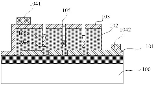
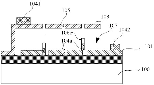
[0004] The object of the present invention is to provide a method for manufacturing a MEMS microphone, which can solve the problem of device defects caused by metal residues at the bottom of the sound hole when the extraction electrode is formed by an etching process

Method used


Image

  • How to make a mems microphone
  • How to make a mems microphone
  • How to make a mems microphone

Examples


Embodiment Construction

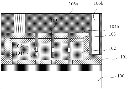
[0028] An existing manufacturing method of a MEMS microphone comprises the following steps:

[0029] First, please refer to figure 1 After making the lower pole plate 101 on the substrate 100, the sacrificial layer 102 and the upper pole plate 103 will be fabricated, and a number of acoustic holes 105 will be formed. Layer 102.

[0030] Then, please continue to refer to figure 1 , a metal layer with a certain thickness will be deposited on the upper pole plate 103 and the sacrificial layer 102 exposed by the upper pole plate 103 and the lower pole plate 101, and a part 104b of the metal layer will cover the surfaces of the upper pole plate 103 and the lower pole plate 101 , the other part 104a will be filled in the acoustic hole 105.

[0031] Next, please continue to refer to figure 1 , forming a photoresist layer on the metal layer, the photoresist layer will fill the acoustic hole 105, and partially expose the photoresist layer. After exposure, the photoresist layer i...


PUM


Abstract

The invention provides a manufacturing method of an MEMS microphone. The method comprises: sequentially forming an extraction electrode layer and a photoresist layer; then exposing a photoresist layerfor the first time and defining an area where the extraction electrode is to be formed; performing secondary exposure on a sound hole area; after the photoresist layer is developed, removing redundant photoresist layer in the sound hole and other areas and only keeping the photoresist layer in the area where the extraction electrode is to be formed. Therefore, the unexposed photoresist residue ofthe sound hole after development is avoided; when continuously taking the patterned photoresist layer as a mask to etch the extraction electrode layer to form the extraction electrode, the extractionelectrode layer in the sound hole can also be removed, so that the extraction electrode layer in the sound hole is prevented from remaining, the problem that after the sacrificial layer is removed, due to the fact that the extraction electrode layer at the bottom of the sound hole adheres to the inner surface of the cavity, MEMS microphone defects are caused can be solved, and the product yield is improved.

Description

technical field [0001] The invention relates to the technical field of manufacturing MEMS devices, in particular to a method for manufacturing a MEMS microphone. Background technique [0002] Micro-Electro-Mechanical-System Microphone (MEMS Microphone), also known as silicon-based condenser microphone, is the most widely used microphone with better performance, hereinafter referred to as MEMS microphone. MEMS microphone is an electro-acoustic transducer made by micromachining technology, which has the characteristics of small size, good frequency response characteristics, and low noise. [0003] In the existing MEMS microphone manufacturing process, when making the lead-out electrodes that are used to lead the upper plate and the lower plate outward, metal is generally deposited on the surface of the upper plate and the lower plate exposed by the upper plate. layer, and then use photolithography combined with etching to etch the metal layer to form the lead-out electrode in...

Claims


Application Information

Patent Timeline
Patent Type & Authority Patents(China)
IPC IPC(8): H04R31/00H04R19/04H04R19/00
CPCH04R19/005H04R19/04H04R31/00H04R2201/003H04R2231/00H04R2410/00
Inventor 闾新明魏丹珠艾俊
Owner SEMICON MFG ELECTRONICS (SHAOXING) CORP
Learn More