Concrete pipe gallery inner mold in-place and demolding method

A technology of concrete and internal mold, which is applied in formwork/formwork/work frame, water conservancy projects, artificial islands, etc. It can solve the problems of long disassembly and assembly time, high manual labor intensity of steel molds, and poor quality of concrete molding, etc., to achieve The effect of enhancing strength

Active Publication Date: 2020-10-09
ERCHU CO LTD OF CHINA RAILWAY TUNNEL GRP +1
View PDF8 Cites 4 Cited by
  • Summary
  • Abstract
  • Description
  • Claims
  • Application Information

AI Technical Summary

Problems solved by technology

[0003] The purpose of the present invention is to overcome the deficiencies of the prior art, and provide a method for the placement and demoulding of the inner mold of the concrete pipe gallery, so as to solve the problems of high manual labor intensity of wooden and steel molds used in the construction of the pipe gallery, poor concrete forming quality, Long disassembly and assembly time, low degree of mechanization, etc., to ensure the quality of concrete molding, ensure the construction period, and reduce the cost of the project

Method used


Image

  • Concrete pipe gallery inner mold in-place and demolding method
  • Concrete pipe gallery inner mold in-place and demolding method
  • Concrete pipe gallery inner mold in-place and demolding method

Examples


Embodiment 1

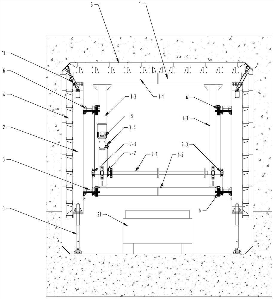
[0059] A mechanized equipment for the construction of a concrete pipe gallery includes: an inner formwork frame part and a lifting trolley part for moving the inner formwork frame in place.

[0060] See attached Figure 1-5 , The inner mold frame part includes a door frame 1, a movable column 2, a column lifting support leg 3, a side template 4, a top template 5, and a translation drive 6, a transmission assembly and a motor 8.

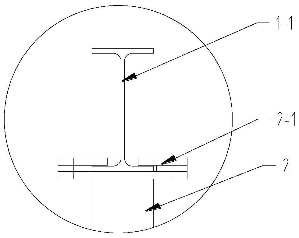
[0061] The door frame 1 is composed of a top door beam 1-1, a bottom cross brace 1-2 and a side vertical brace 1-3. The top door beam is made of H-shaped steel or steel plate welded into an H shape, which can be formed by multi-section bolting. , To meet the use of sections of different widths; the side vertical braces 1-3 are fixedly arranged between the top door beam 1-1 and the bottom cross brace 1-2 to connect the top door beam and the bottom cross brace. A side vertical support 1-3 is arranged on each side of the bottom transverse support;

[0062] The...

Embodiment 2

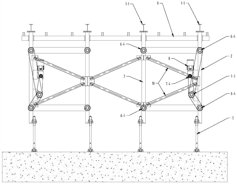
[0077] On the basis of the first embodiment, further, the inner mold base can be longitudinally spliced ​​into the required size by multiple inner mold base units to meet different construction needs. Each inner mold base unit can realize a motor 8 at the same time. The eight translation drivers 6 are driven to act in synchronization. Two specifics: each inner mold base unit includes two door frames 1, four movable columns 2, eight translation drives 6, a motor 8 and a transmission shaft 7-1.

[0078] The two masts are arranged longitudinally at intervals in the front and rear, and a movable column is arranged on each side of the horizontal (width direction) of each mast. The two front and rear movable columns on the same side are connected by a longitudinal beam 9 and a scissor support 10, In order to stabilize the structure and prevent the inner mold base unit from being deformed by force, each movable column 2 is connected to the door frame part of its inner side by two transl...

Embodiment 3

[0080] On the basis of the first embodiment, further, see the attached Figure 8 The specific installation structure of the thrust bearing seat 6-3 and the rotating nut 6-2 of the translation drive 6 is: one end of the rotating nut 6-2 has a flange 6-21; the thrust bearing seat 6-3 includes The upper cover 6-31 and the base 6-32, the upper cover 6-31 and the base 6-32 are connected together by bolts, an installation cavity is formed between the upper cover 6-31 and the base 6-32, the rotating nut 6 The flange 6-21 of 2 is installed in the mounting cavity, and a number of rings are provided between the upper surface of the flange 6-21 of the rotating nut 6-2 and the upper cover 6-31 of the thrust bearing seat 6-3 The ball 6-3a, the lower surface of the flange 6-21 of the rotating nut 6-2 and the base 6-32 of the thrust bearing seat 6-3 are also provided with several circles of balls 6-3b, and the wings of the rotating nut 6-2 Several rings of balls 6-3c are also arranged between...


PUM


Abstract

The invention discloses a concrete pipe gallery inner mold in-place and demolding method. The concrete pipe gallery inner mold in-place and demolding method comprises an inner mold frame and a liftingtrolley used for moving the inner mold frame in place, the inner mold frame comprises a portal frame, movable stand columns are arranged on the two sides of the portal frame, side mold plates are installed on the movable stand columns, and the movable stand columns are connected with the portal frame through translation drivers; a top mold plate is mounted at the top of the portal frame; stand column lifting supporting legs are arranged at the bottoms of the movable stand columns, and the height of the whole inner mold frame is adjusted through the stand column lifting supporting legs; and bottom middle supporting legs capable of rising and falling are further arranged at the bottom of the portal frame. During construction, the lifting trolley lifts the inner mold frame to move and be preliminarily in place, the position and the height of the side mold plate are adjusted by combining the inner mold frame, and mold erecting and demolding work is achieved.

Description

Technical field [0001] The invention belongs to the technical field of pipe gallery concrete construction, and specifically relates to a method for placing and demoulding an inner form of a concrete pipe gallery. Background technique [0002] With the rapid development of urbanization, urban land resources are becoming more and more tense, and urban construction projects and public facilities are increasing, especially in the construction of various pipelines. If the planning and design are not proper, the problem of repeated excavation will occur. It will not only affect the normal traffic in the city, but also affect the service life of various pipelines. Through the application of integrated pipe gallery construction technology, the above problems can be effectively solved and the safe operation of various pipelines can be ensured. Existing pipe gallery concrete construction mostly uses wood molds, steel molds, etc. The disassembly and assembly time is long, and the formwork ...

Claims


Application Information

Patent Timeline
Patent Type & Authority Applications(China)
IPC IPC(8): E02D29/045E04G13/00
CPCE02D29/10E04G13/00
Inventor 董志伟哈建波梁云生任勇吴相斌刘伟刘兴波李书森申达李志军邓毛毛洪开荣黄世伟王秋林陈素兰段浩鹏王雅楠张辰田陈海建吴志刚
Owner ERCHU CO LTD OF CHINA RAILWAY TUNNEL GRP
Why Eureka
Try Eureka