A long-stroke position detection device and method

A detection device and long-stroke technology, applied in the direction of measuring device, using electrical device, using electromagnetic/magnetic device to transmit sensing components, etc., can solve the problems such as difficulty in ensuring uniformity of magnets and devices, complicated circuit cost, limited detection accuracy, etc. , to achieve the effect of low power consumption, reduced complexity and high linearity

Active Publication Date: 2021-07-16
南京迅传智能工业技术有限公司
View PDF10 Cites 0 Cited by
  • Summary
  • Abstract
  • Description
  • Claims
  • Application Information

AI Technical Summary

Problems solved by technology

However, the Hall device is sensitive to unsaturated magnetic fields, and there must be harmonic components in the magnetic field of the magnet. It is also difficult to ensure a uniform air gap between the magnet and the device, and the superposition of the external stray magnetic field affects the detection accuracy of this method.
Patent CN 101915590 B proposes a magnetoresistive array-based position detection system, which obtains the position of the movable member by signal processing of the unequal-distance magnetoresistive sensing components, but this method is not suitable for long-stroke detection because each The magnetoresistive components need to be associated with the corresponding integrated circuits in multiple chip carriers, and a large number of analog signal conditioning and ADC converter channels are required under long strokes, resulting in circuits that are too complex and costly to be practically applied

Method used


Image

  • A long-stroke position detection device and method
  • A long-stroke position detection device and method
  • A long-stroke position detection device and method

Examples


Embodiment 1

[0090] Taking a single detection circuit board composed of four magnetic sensor arrays as an example, when the permanent magnets are in different positions, the corresponding magnetic sensor gating and detection methods are described as follows Figure 5 shown. The four magnetic sensors in the figure are marked as 1#, 2#, 3# and 4#, of which 1# is the first magnetic sensor of the detection circuit board, and the center position of the corresponding sensor is L 1 , L 2 , L 3 and L 4 is a known or calibrated position, position L 1 It is the coordinate zero point, which corresponds to four sensor output curves. Taking the permanent magnets in the four positions of A, B, C and D as an example, the collection and control process is as follows:

[0091] First, select sensors 1#, 2#, 3# and 4# in turn and perform initial position detection, then enter the continuous sampling process. When the permanent magnet is at position A, the power supply and output signal of sensor 1# and...

Embodiment 2

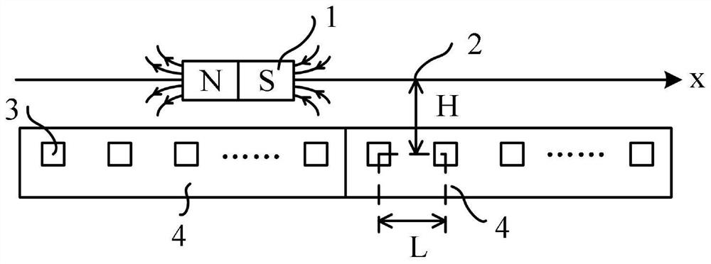
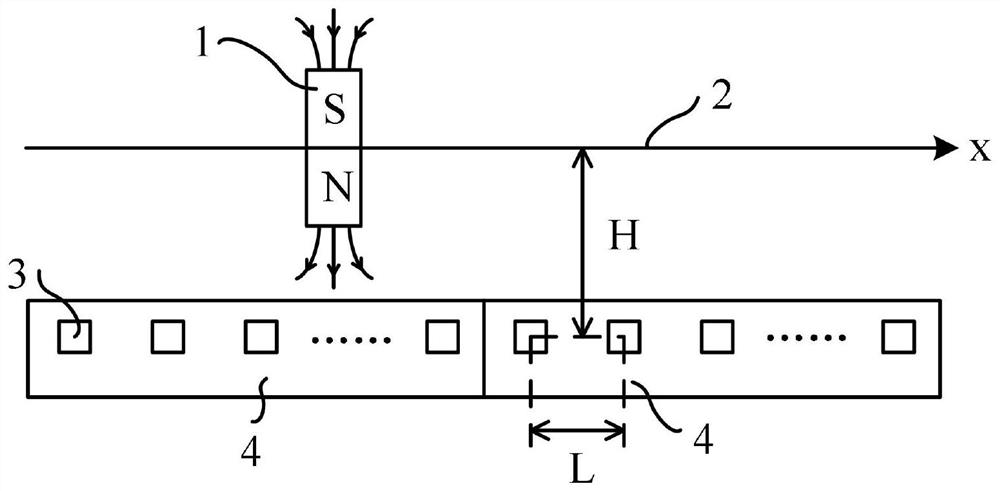
[0101] When multiple detection circuit boards are connected in series for long-stroke position detection, such as Image 6 As shown, the embodiment is spliced ​​end to end by the first detection circuit board 41 and the second detection circuit board 42, the magnetic sensor 1# is the last sensor of the magnetic sensor array of the first detection circuit board 41, and the magnetic sensor 2# is the second detection circuit board 41. The first sensor of the circuit board 42 sensor array, the center positions of the sensors are respectively L 1 and L 2 , is a known or calibrated position, corresponding to two sensor output curves. Taking the permanent magnets at positions A and B in the middle of two circuit boards as an example, the collection and control process is as follows:

[0102] When the permanent magnet is in position A, the detection circuit board 1 selects the sensor 1# and the sensor power supply and output signal adjacent to the left side of 1#, and collects synch...


PUM


Abstract

The invention relates to a long-stroke position detection device and method. The detection device includes a permanent magnet and a detection circuit board; the permanent magnet is fixedly installed on a movable component at a position to be detected, and linearly displaces with the movable component; the detection circuit board detects the position of the permanent magnet in real time. Wherein, the detection circuit board is a PCB board including a magnetic sensor array, a multiplex gate module and a microprocessor module. By adopting the magnetic sensor array, the present invention can reduce the error caused by uneven air gap while avoiding the influence of the magnetic field harmonic and the external stray magnetic field on the detection accuracy, and has the advantage of high linearity. By using the multi-channel gating module and the microprocessor module, only the analog signal output by the magnetic sensor array that is close to or about to be close to the current position to be measured is gated, and the synchronous analog-to-digital converter is reduced while ensuring the real-time detection The number of channels and the complexity of the conditioning circuit structure, and achieve low power consumption.

Description

technical field [0001] The invention relates to the field of long-stroke position detection, in particular to a long-stroke position detection device and method. Background technique [0002] In the field of industrial control, it is often necessary to accurately detect the position of movable components in a non-contact manner for closed-loop feedback of the system. In short-stroke position detection, this technology is relatively mature, and detection components such as grating scales and magnetic scales have been widely used. However, in the field of long-stroke motion control, such as electromagnetic ejection devices, linear transmission devices based on segmented linear motors, etc., since their movable components are often passive, their position detection methods will be greatly limited. Patent CN 109217767A proposes a linear displacement detection method based on a grating or magnetic grating encoder for a linear transmission system. The scale is placed on the mover...

Claims


Application Information

Patent Timeline
Patent Type & Authority Patents(China)
IPC IPC(8): G01D5/14G01B7/00
CPCG01B7/00G01D5/14
Inventor 黄旭珍王安鹏黄倩丁徐哲
Owner 南京迅传智能工业技术有限公司
Why Eureka
Try Eureka