
Compact infrared viewfinder optical system based on free-form surface prism

A curved prism and optical system technology, applied in viewfinders, optics, prisms, etc., can solve the problem that the imaging quality can only be used for the visual system, does not substantially correct the system chromatic aberration, and does not involve dual-band receiving imaging, etc. The overall structure is compact and lightweight, reducing off-axis field of view aberration, and the effect of compact structure

Active Publication Date: 2020-10-09
TONGJI UNIV
View PDF30 Cites 5 Cited by
  • Summary
  • Abstract
  • Description
  • Claims
  • Application Information

AI Technical Summary

Problems solved by technology

[0003] In "Monolithic freeform element" (Proc.SPIE 9575, 95750G, 2015), S.R.Kiontke developed a free-form surface prism lens with a field of view of 24° and a length of 22mm. The material is germanium, and its working band is the long-wave infrared band. However, the optical system used by this lens is a single-channel long-wave infrared system, and the system chromatic aberration is not substantially corrected, so the imaging quality is not ideal; using two freeform prisms" (COL 11(3), 031201, 2013) mentioned four dual-focal plane head-up display visual system designs, but these design configurations did not involve dual-band receiving imaging, and the final Image quality can only be used with vision systems

Method used


Image

  • Compact infrared viewfinder optical system based on free-form surface prism
  • Compact infrared viewfinder optical system based on free-form surface prism
  • Compact infrared viewfinder optical system based on free-form surface prism

Examples


Embodiment Construction

[0026] The present invention will be described in detail below in conjunction with the accompanying drawings and specific embodiments. This embodiment is carried out on the premise of the technical solution of the present invention, and detailed implementation and specific operation process are given, but the protection scope of the present invention is not limited to the following embodiments.

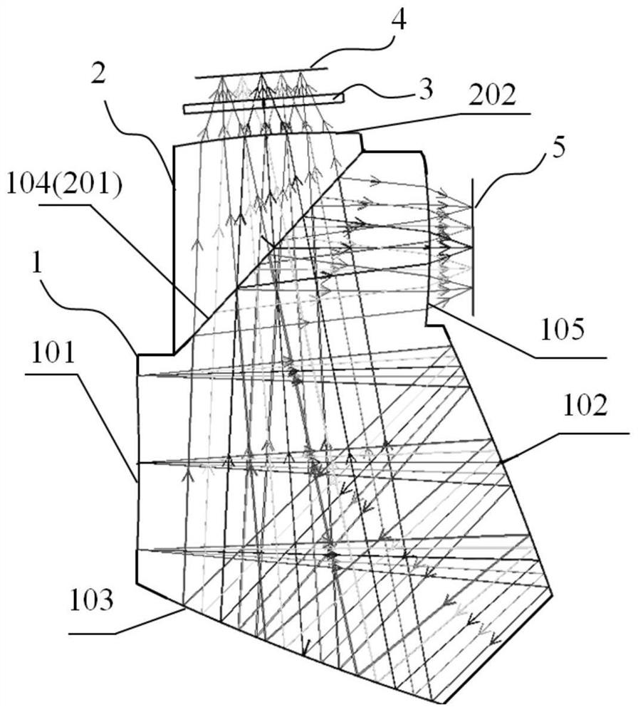
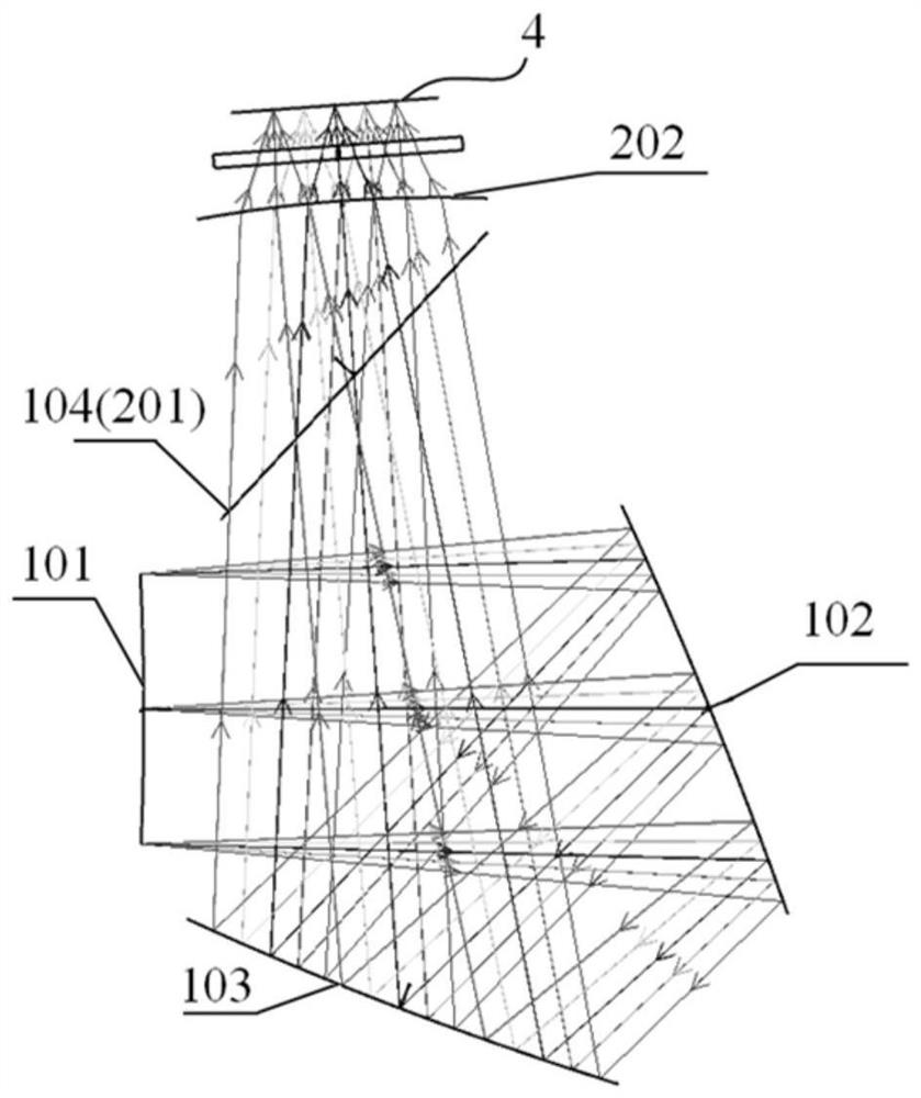
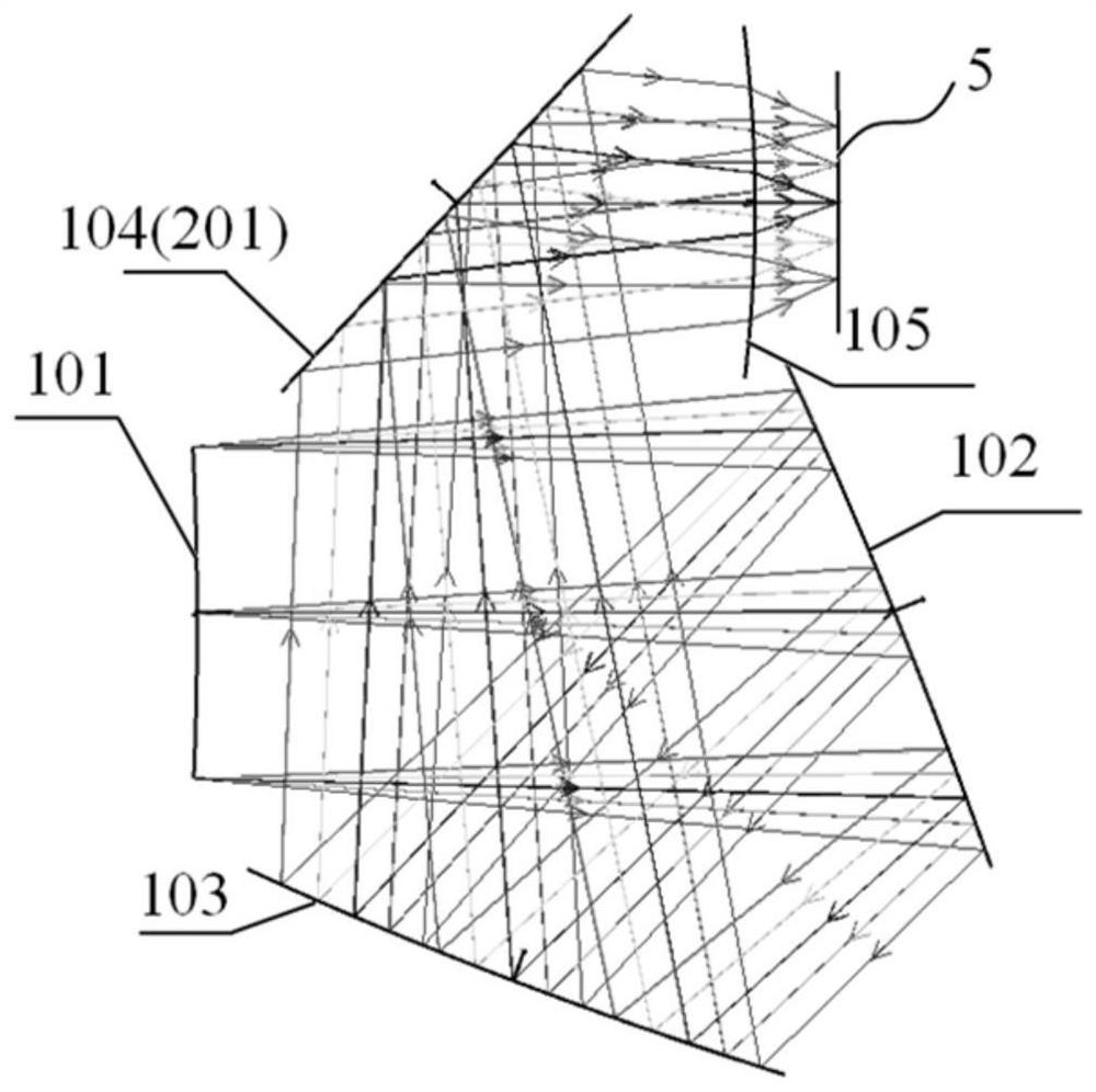
[0027] A compact infrared viewfinder optical system based on a free-form prism, such as figure 1 , including a free-form surface prism 1, a triangular prism 2, a narrow-band filter 3, a near-infrared detector 4 and a long-wave infrared detector 5, and the free-form surface prism 1 includes a high-order aspheric surface 101 connected in sequence, a second reflection free-form surface 103 1. Reflecting the free-form surface 102 and the beam-splitting plane 104 for the first time, the beam-splitting plane 104 is an inclined plane, and satisfies the total reflection condition of long-wave...


PUM

PropertyMeasurementUnit
Diameteraaaaaaaaaa

Abstract

The invention relates to a compact infrared viewfinder optical system based on a free-form surface prism. The dsystem comprises a free-form surface prism, a triangular prism, a narrow-band optical filter, a near-infrared detector and a long-wave infrared detector; the free-form surface prism comprises a high-order aspheric surface, a second-order reflection free-form surface, a first-order reflection free-form surface and a light splitting plane which are connected in sequence; incident light is incident through the high-order aspheric surface and then sequentially reflected through the reflection free-form surface and the second reflection free-form surface. When reaching the light splitting plane, the light is divided into near-infrared light and long-wave infrared light, the near-infrared light is transmitted and then reaches the near-infrared detector after sequentially passing through the triangular prism and the narrow-band filter, and the long-wave infrared light is reflected and then emitted from the diffraction plane and reaches the long-wave infrared detector. Compared with the prior art, the system has the advantages of good imaging quality, compact structure and the like.

Description

technical field [0001] The invention relates to the field of optical system and device design, in particular to a compact infrared viewfinder optical system based on a free-form surface prism. Background technique [0002] The dual-band imaging system can simultaneously obtain detection data in two bands for the same target, effectively suppress the interference information of the complex background, and improve the accuracy of target observation. A general dual-band imaging system is mainly composed of three ways: the first is to use two independent single-band imaging systems; the second is to share an optical system with two detectors responding to different bands; the third is to use a Two-color infrared detectors responding to two wavelength bands share a single optical system. The former method requires the design of two independent imaging systems, and the latter two methods require the design of a broadband achromatic system, generally using a purely reflective stru...

Claims


Application Information

Patent Timeline
IPC IPC(8): G02B5/04G02B17/08G02B27/10G03B13/02
CPCG02B5/04G02B17/086G02B27/1006G03B13/02
Inventor 王占山余俊沈正祥王旭
Owner TONGJI UNIV
Learn More