Waveguide grating antenna for phased array transmitting array and forming method of waveguide grating antenna

A waveguide grating and emission array technology, applied in the field of waveguide grating antenna and its formation, can solve the problems of increasing the detection distance of the phased array and low emission efficiency, and achieve the effects of improving emission efficiency, reducing leakage, and increasing the ratio

Active Publication Date: 2020-10-09
SHANGHAI IND U TECH RES INST
View PDF8 Cites 9 Cited by
  • Summary
  • Abstract
  • Description
  • Claims
  • Application Information

AI Technical Summary

Problems solved by technology

[0006] The invention provides a waveguide grating antenna for a phased array transmitting array and a forming method thereof, which are used to solve the problem of low transmitting efficiency of the existing phased array transmitting array, so as to increase the detection distance of the phased array

Method used


Image

  • Waveguide grating antenna for phased array transmitting array and forming method of waveguide grating antenna
  • Waveguide grating antenna for phased array transmitting array and forming method of waveguide grating antenna
  • Waveguide grating antenna for phased array transmitting array and forming method of waveguide grating antenna

Examples


Embodiment Construction

[0032] The specific implementation of the waveguide grating antenna for phased array transmitting array and its forming method provided by the present invention will be described in detail below with reference to the accompanying drawings.

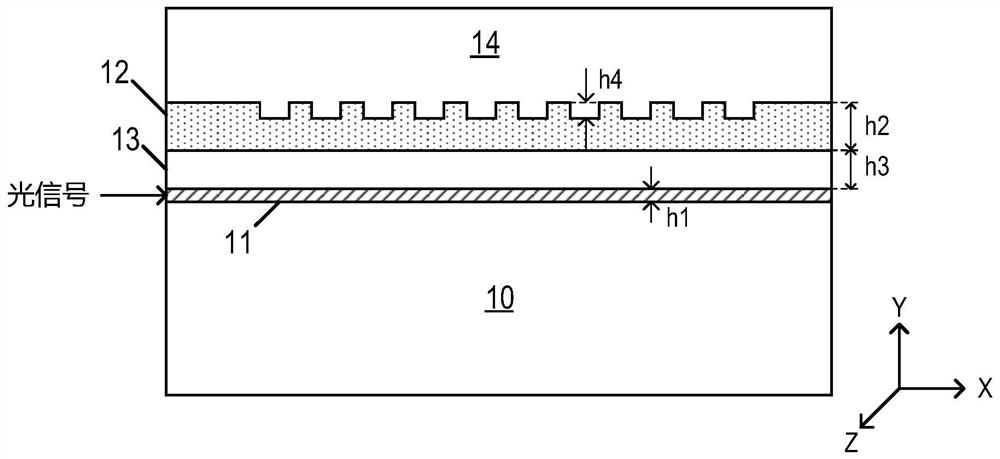
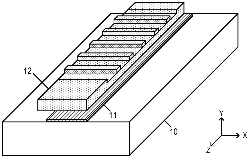
[0033] This specific embodiment provides a waveguide grating antenna for a phased array transmitting array, with figure 1 It is a cross-sectional schematic diagram of a waveguide grating antenna used for a phased array transmitting array in a specific embodiment of the present invention, with figure 2 It is a three-dimensional perspective view of the waveguide grating antenna used for the phased array transmitting array in the specific embodiment of the present invention.

[0034] Such as figure 1 , figure 2 As shown, the waveguide grating antenna for the phased array transmitting array provided in this specific embodiment includes:

[0035] Substrate 10;

[0036] The first waveguide layer 11 is located on the surface of the substrat...


PUM

PropertyMeasurementUnit
thicknessaaaaaaaaaa

Abstract

The invention relates to the field of integrated photonic devices, in particular to a waveguide grating antenna for a phased array transmitting array and a forming method of the waveguide grating antenna. The waveguide grating antenna of the phased array transmitting array comprises a substrate; a first waveguide layer which is positioned on the surface of the substrate; a second waveguide layer which is arranged above the first waveguide layer in the direction perpendicular to the substrate, wherein a grating structure is arranged in the second waveguide layer; evanescent wave coupling can becarried out between the first waveguide layer and the second waveguide layer, so that the length of the grating can be controlled to increase the resolution of the phased array, the asymmetry in thevertical direction is improved, and the directivity of the waveguide grating antenna is improved. According to the invention, the leakage of light to the substrate is reduced, the proportion of upwardemission of light is improved, the emission efficiency of light and the detection distance of the phased array are further improved, and the realization of a high-power output device is facilitated.

Description

technical field [0001] The invention relates to the field of integrated photonic devices, in particular to a waveguide grating antenna for a phased array emitting array and a forming method thereof. Background technique [0002] LiDAR has attracted a lot of attention in recent years. Traditional lidar usually uses mechanical devices to deflect the beam. However, due to the limitation of the structure of the mechanical device itself, the scanning speed of the beam is greatly limited. And because the laser radar realized by the mechanical device is generally large in size, it can only be installed on the roof of the car, which greatly affects the appearance of the car. In addition, due to size and weight limitations, traditional lidar cannot be used for some smaller applications such as drones. Since the lasers and detectors in the lidar with mechanical devices need to be aligned one by one, this also limits the output of the lidar to a certain extent, making the traditiona...

Claims


Application Information

Patent Timeline
Patent Type & Authority Applications(China)
IPC IPC(8): G02B6/124G02B6/13
CPCG02B6/124G02B6/13
Inventor 王庆汪巍方青涂芝娟曾友宏蔡艳王书晓余明斌
Owner SHANGHAI IND U TECH RES INST
Why Eureka
Try Eureka