
Touch device and manufacturing method thereof

A technology of a touch control device and a manufacturing method, which are applied in the fields of instruments, electrical digital data processing, electrical components, etc., can solve the problems of limited reduction of the wiring area and the inability of the wirings to be too close together.

Active Publication Date: 2020-10-09
INTERFACE TECH CHENGDU CO LTD +2
View PDF13 Cites 2 Cited by
  • Summary
  • Abstract
  • Description
  • Claims
  • Application Information

AI Technical Summary

Problems solved by technology

However, the disadvantage of this method is that the degree of reduction is easily affected by material resolution, substrate expansion and contraction, equipment accuracy, resolution, process stability, and environmental cleanliness, and the wiring cannot be too close to each other, so that the wiring Area reduction is still quite limited

Method used


Image

  • Touch device and manufacturing method thereof
  • Touch device and manufacturing method thereof
  • Touch device and manufacturing method thereof

Examples


Embodiment Construction

[0059] The present invention can provide a touch device, through a special structural design and hot-press bonding technology, so that the traces are completely attached to the side walls of the touch module and the display module, and there is no need to use the base material to protect the traces. Line, so that the bending radius of the line is not affected by the thickness and bendability of the substrate, which can greatly reduce the wiring area of ​​the line and achieve the purpose of narrow frame.

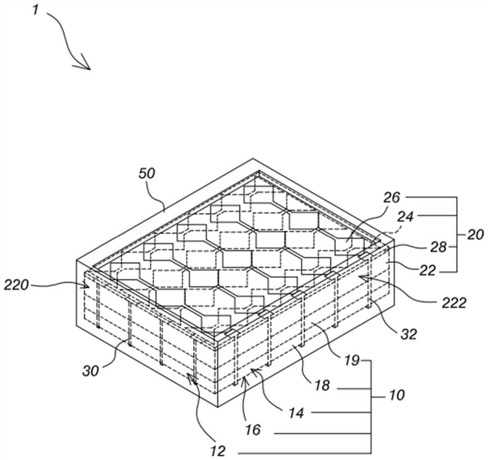
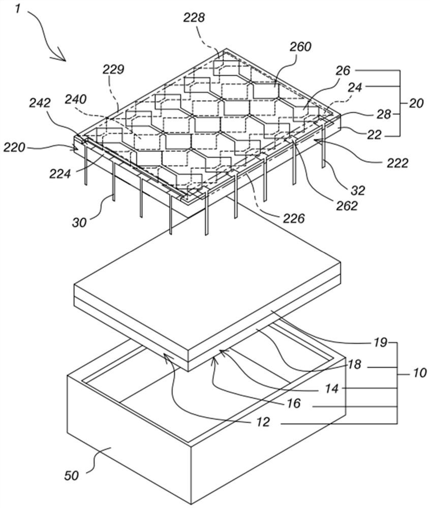
[0060] In order to better understand how the present invention achieves the above effects, the technology of the touch device and its manufacturing method is described in detail here, please refer to Figure 2 to Figure 5 Firstly, the structure of the touch device 1 is described. The touch device 1 includes a display module 10 , a touch module 20 , a plurality of first wires 30 and a plurality of second wires 32 . The touch module 20 is disposed on the display module 10 , and...


PUM


Abstract

The invention relates to a touch device and a manufacturing method thereof. The method comprises the following steps of fixing a release film with a plurality of first wires and second wires on a touch module by using a three-dimensional hot pressing technology; allowing the plurality of first wires to extend to the first side surface of the touch module and be electrically connected with a firstconductive pad of the touch module, and allowing the plurality of second wires to extend to the second side surface of the touch module and be electrically connected with a second conductive pad of the touch module; and removing the release film, irradiating by using a curing lamp to cure the wires, and coating by using a shell. According to the invention, the wires can be tightly attached to theside edge of the touch module through a hot-pressing attaching technology so that the wiring area is greatly reduced, and the purpose of a narrow frame is achieved.

Description

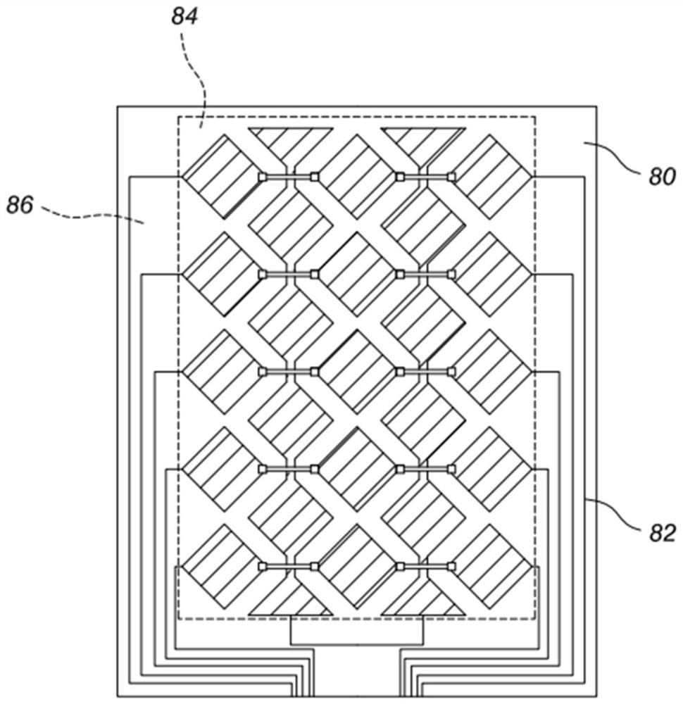
technical field [0001] The present invention relates to a display technology, in particular to a touch device and a manufacturing method thereof. Background technique [0002] With the advancement of technology, the functions of portable electronic devices such as smart phones and tablet computers are becoming more and more powerful. The requirements for thinness and portability of electronic devices are gradually increasing. [0003] As a result, many manufacturers began to reduce the components of portable electronic devices, such as making smaller but more powerful semiconductor components. In addition, many manufacturers have also begun to reduce the wiring area of ​​the outer frame of the touch screen of the portable electronic device. This design modification can not only make the portable electronic device thinner and lighter, but also expand the area of ​​the screen. . [0004] Please refer to figure 1 Generally, the touch screen 80 has a visible area 84 and a no...

Claims


Application Information

Patent Timeline
Patent Type & Authority Applications(China)
IPC IPC(8): G06F3/041H01L27/32
CPCG06F3/0412H01L27/156G06F2203/04103H10K59/40H10K59/10
Inventor 王进立洪裕民
Owner INTERFACE TECH CHENGDU CO LTD
Learn More