Electrode and method of making same

a technology of electrodes and electrodes, applied in the direction of welding/cutting media/materials, manufacturing tools, welding apparatus, etc., can solve the problems of inability to filling or alloying agents, inability to resist moisture contamination and physical damage to fluxes, etc., to reduce reduce the cross-sectional area of wires, and increase resistance in the regions of indentations 10

Inactive Publication Date: 2001-01-30
LINCOLN GLOBAL INC
View PDF9 Cites 10 Cited by
  • Summary
  • Abstract
  • Description
  • Claims
  • Application Information

AI Technical Summary

Benefits of technology

One procedure for accomplishing the indentations 10 is schematically illustrated in FIGS. 3, 3A and 4 wherein forming wheels 50, 52 are located adjacent to the outlet of wire extruder producing wire SW or adjacent to a roll of wire SW. Wheels 50, 52 have a series of circumferentially spaced cavities 70, 72 coming together at joint 74, as shown in FIG. 3A to upset wire SW at axially spaced locations and reform rectangular wire SW into a generally cylindrical wire W having axially spaced indentations 10. Relief areas 80, 82 are provided on wheels 50, 52, respectively for accommodating spaced, quantized segments Q to produce a wire W, as shown in FIG. 2. Forming wheels 50, 52 could be located adjacent the welding operation in front of the wire feeder for driving welding wire W to the welding area. In this manner, an operator could customize the size of segments Q and the configuration of indentations 10 with respect to the actual welding process to be performed. A different set of wheels 50, 52 could be provided for various welding operations. A standard wire SW could be provided to the welding locations and the quantized segments Q would be formed on the wire at that site. This is an advantage of the present invention and allows customized production of a solid welding wire having quantized segments Q separated by bridging elements B. Other arrangements could be provided for creating the indentations 10, such as laser cutters, end mills, saws, etc.
and allows customized production of a solid welding wire having quantized segments Q separated by bridging elements B. Other arrangements could be provided for creating the indentations 10, such as laser cutters, end mills, saws, etc.
One advantage of a solid welding wire constructed in accordance with the present invention is that it can be coordinated with a pulse welding process, as schematically illustrated in FIG. 5 wherein a series of current pulses 100 from a constant voltage power supply have a time spacing t.sub.1 to t.sub.2. The pulse frequency of the pulses 100 is a known value, such as X pulses per minute. FIG. 6 illustrates schematically the welding process, wherein wire W is passed through a contact sleeve 110 toward a workpiece 112 so that wire W is melted at arc D by pulses from a power supply connected to negative lead 120 and positive lead 122. As pulses 100 are directed through arc D, wire W is moved at a wire feed speed providing a quantized segment Q at the same time as a current pulse 100. The wire feed speed is coordinated with the frequency of the current pulses so that a quantized amount of metal is provided for each pulse to melt during the pulse welding procedure. Referring to FIG. 7, the relationship between the resistance of the wire along a particular length of the wire as a function of the power P supplied to the wire W is shown. The resistance of a section of wire W is a function of temperature and is represented by R=R.sub.0 +A.times.Temp, wherein R is the resistance of the wire, R.sub.0 is the resistance of the wire and ambient temperature, A is a constant, and Temp is the temperature about ambient temperature. As can be appreciated, during the melting of the wire, the resistance in the regions of the indentations 10 increases due to the reduced cross-sectional area of the wire. The power supplied to the wire is illustrated as being dependant on the cross-sectional area of the wire and is represented by P=I.sup.2 / (100.times.Area.sub.cross), wherein P is the power supplied to the wire, I is the current supplied to the wire and Area.sub.cross is the cross-sectional area of the wire. As the cross-sectional area of the wire is reduced, the amount of current to the wire can be reduced while maintaining a constant amount of power to the wire.
The special shape of the wire results in a change in the arc and the resultant weld. The special shape of the wire controls the transfer of the molten wire through the arc by forcing individual droplet transfer. Each droplet is generally of a fixed size and separates from the wire at a generally precise frequency. This type of droplet transfer occurs because the indented region of the wire melts first. The indented region has a larger resistance due to its smaller cross-sectional area as compared to the non-indented region. Therefore, the heating of the indented region is accelerated because of the larger resistance and resulting higher temperatures during welding. Pinch forces also assist in the droplet transfer. The pinch force is the electromagnetic pressure than constricts the wire during welding. The smaller cross-sectional area at the indented region produces increased pinch forces, thereby assisting in the detachment of the droplet from the wire and assisting to propel the droplet into the arc. The special shaped wire design results in significant advantages over conventional wire. The special shaped wire welds at higher deposition rates than can be achieved with conventional wire. The special shaped wire requires less energy weld as compared to conventional wire. The reduced energy requirements allows for thinner materials to be welded and the reduction in the amount of distortion of the welded materials. The special shaped wire enhances the STT200 process and MIG welding, and increases the deposition rates when welding open root joints such as on pipes. The heat effected zone of the welded materials is reduced when using the special shaped wire thereby resulting in improved mechanical properties of the weld. The use of the special shaped wire also results in cleaner welds due to the generally precise droplet control that results in reduced spatter. The special shaped wire also generated reduced amounts of fumes and soot since the wire is transferred in the form of a droplet instead of being vaporized in the arc. This ability to coordinate specific quantities of metal for each current pulse is an advantage of the present invention. There are other advantages as previously discussed whereby the novel concept of using quantized segments in a solid metal welding wire to produce controlled resistance and superior droplet transfer.
The invention has been described with reference to preferred embodiments and alternates thereof. It is believed that many modifications and alterations to the embodiments discussed herein will readily suggest themselves to those skilled in the art upon reading and understanding the

Problems solved by technology

Thus, moisture contamination and physical damage to the fluxing, filling or alloying agents is inhibited.

Method used


Image

  • Electrode and method of making same
  • Electrode and method of making same
  • Electrode and method of making same

Examples


Embodiment Construction

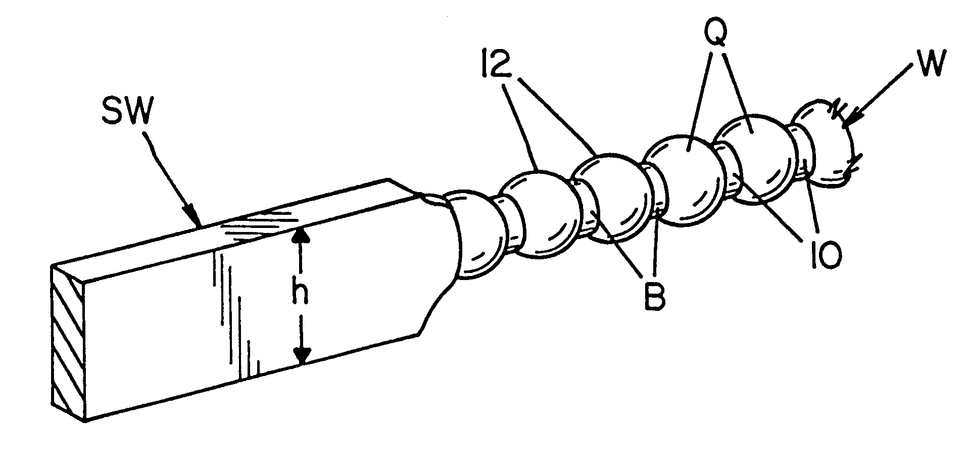
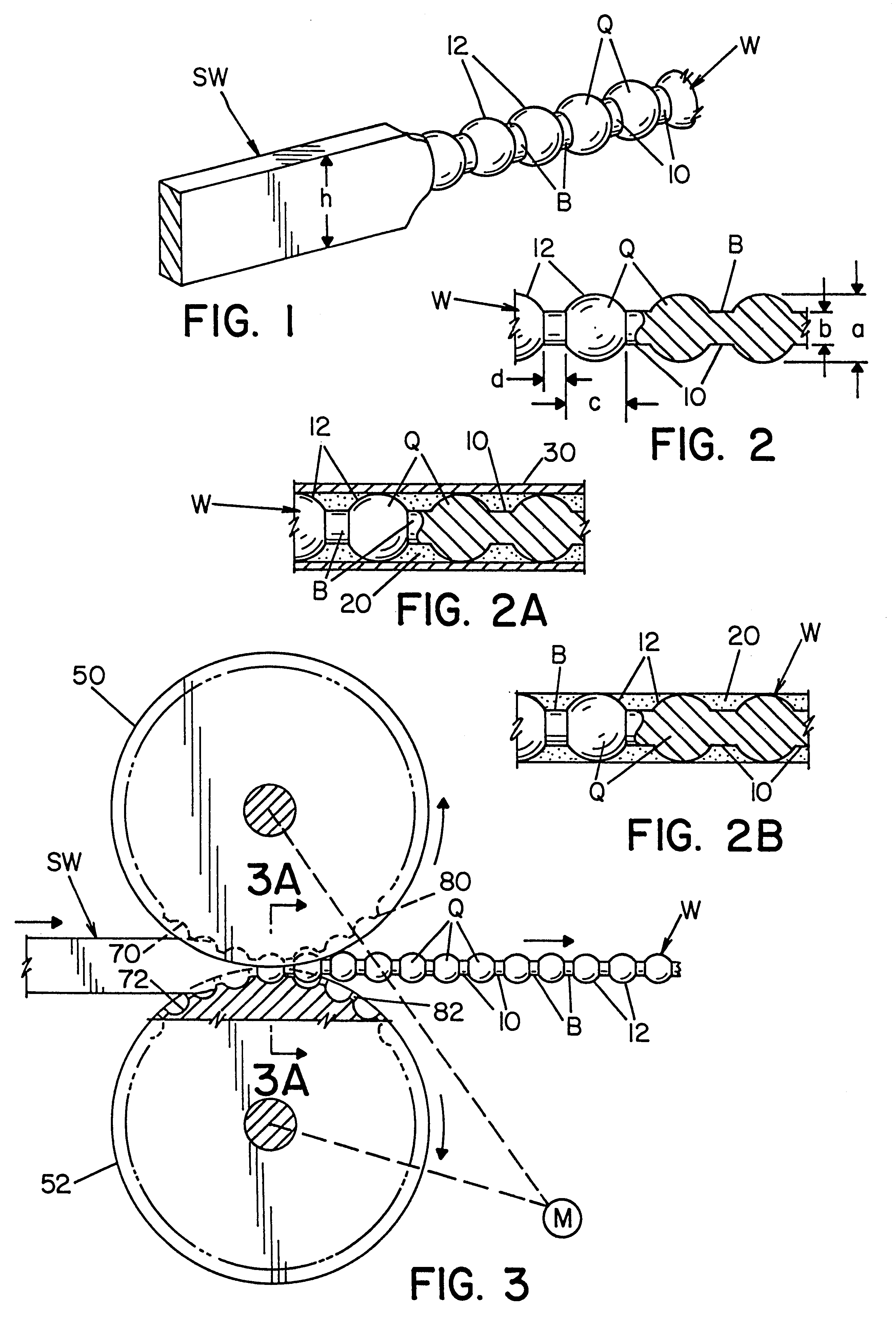
Referring now to the drawings, wherein the showings are for the purpose of illustrating a preferred embodiment of the present invention and not for the purpose of limiting same, FIGS. 1 and 2 show a welding wire W constructed in accordance with the present invention. Wire W is shown to be formed from a standard rectangular wire SW. Wire SW has a major dimension h which represents the height of the rectangular wire. Wire W has a series of distinct, quantized segments Q separated by connecting or bridging elements B. These bridging elements are formed by a series of axially spaced indentations 10 inward of cylindrical surface 12 for welding wire W. Quantized segments Q can take a variety of shapes from cylindrical to spherical and connecting elements B can have a variety of shapes determined by indentations 10 or other groove like modifications extending inwardly of surface 12. In accordance with the invention, quantized segments Q have a maximum dimension a of wire W. Wire W is forme...


PUM

PropertyMeasurementUnit
outer diameteraaaaaaaaaa
lengthaaaaaaaaaa
diameteraaaaaaaaaa

Abstract

A welding wire for use in electric arc welding and method of making same, wherein the wire has an effective outer diameter and comprises a length of solid metal formed into a series of distinct segments each having a selected volume and having an indented and non-indented region with the cross sectional area of the solid metal at said non-indented region being greater than the cross sectional area of the solid metal at the indented region.

Description

The present invention relates to the art of electric arc welding of the type where a welding wire is directed toward a workpiece and an electrical current is passed through the welding wire to the workpiece to create an arc welding process melting the end of the advancing wire and depositing the melted metal onto the workpiece and more particularly to an improved welding wire for use in this arc welding process and the method of making this improved welding wire.INCORPORATION BY REFERENCEU.S. patent application Ser. No. 024,392 filed Feb. 17, 1998 is incorporated by reference herein to provide information on solid metal welding wire which has distinct quantized segments that facilitate superior droplet transfer.BACKGROUND OF INVENTIONElectric arc welding of the type to which the present invention is directed involves the use of a welding wire normally stored upon a spool or reel, which wire is fed from the supply reel toward a workpiece through a tubular connector so that current ca...

Claims


Application Information

Patent Timeline
Patent Type & Authority Patents(United States)
IPC IPC(8): B23K35/02B23K35/00B23K35/40B23K9/24B23K9/09B23K35/04B23K35/36
CPCB23K9/24B23K35/0261B23K35/40B23K35/0266
Inventor BLANKENSHIP, GEORGE D.ENYEDY, EDWARD A.
Owner LINCOLN GLOBAL INC
Why Eureka
Try Eureka