Visual intramedullary nail distal-end collimator

A technology of intramedullary nails and collimators, applied in internal fixers, internal bone synthesis, medical science, etc., can solve the problems of difficult adjustment and distal aiming, and achieve improved operation speed, reduced fluoroscopy times, and simplified structure Effect

Pending Publication Date: 2020-10-13
陈聚伍 +1
View PDF2 Cites 0 Cited by
  • Summary
  • Abstract
  • Description
  • Claims
  • Application Information

AI Technical Summary

Problems solved by technology

[0005] The present invention aims at the problem that the distal aiming is difficult or the adjustment is difficult in the existing intramedullary nail collimator, and provides a highly integrated, simplified structure, easy to adjust, which can lift, traverse and horizontally angle the aiming reference mechanism. Adjustment, and use the height reference needle and translation angle reference needle located outside the body as a reference to adjust under fluoroscopy conditions, coincide with the projection of the distal fixation hole of the intramedullary nail as the adjustment purpose, and then punch and fix it to achieve accurate visualization of the distal end of the intramedullary nail aiming operation

Method used


Image

  • Visual intramedullary nail distal-end collimator
  • Visual intramedullary nail distal-end collimator
  • Visual intramedullary nail distal-end collimator

Examples


Embodiment 1

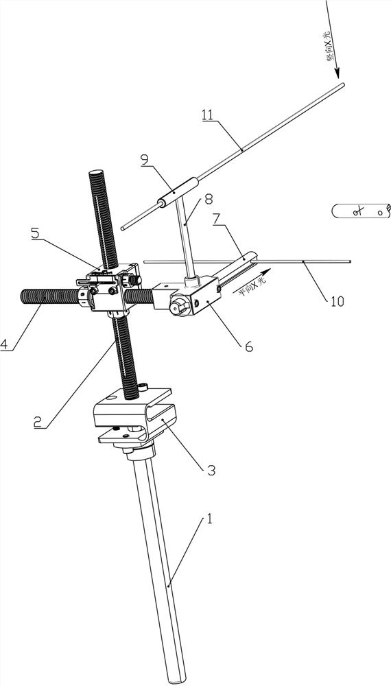
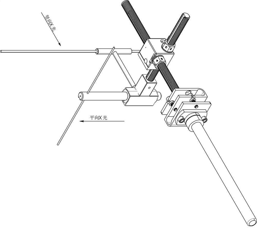
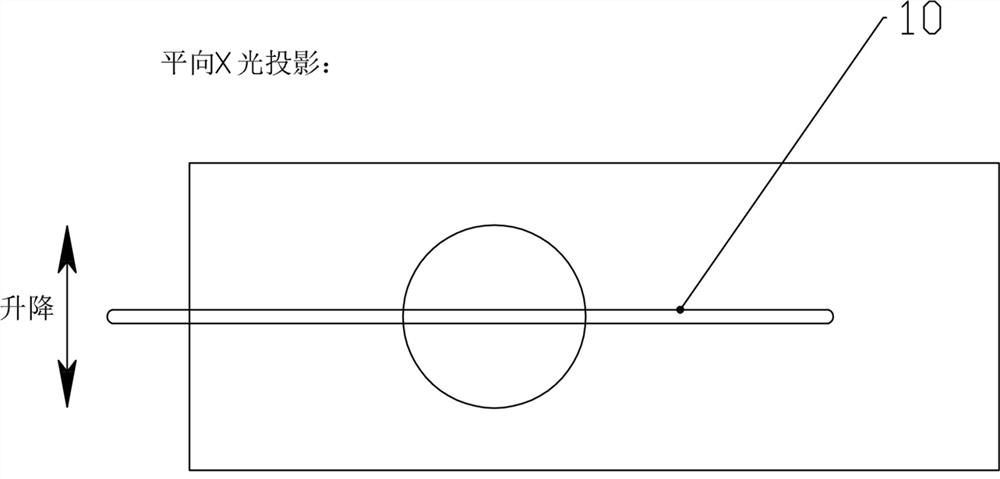
[0048] Example 1: Using a figure 1 The visualized distal intramedullary nail sight is shown to target the keyhole of the distal end of the intramedullary nail. Although the distal hole of the intramedullary nail is located in the medullary cavity and cannot be directly observed, under the condition of C-arm fluoroscopy, the height can be adjusted by The reference needle 10 and the translation angle are adjusted with reference to the needle 11, so that the sight installation sleeve can be adjusted synchronously, and finally the axis of the sight installation sleeve corresponds to the axis of the distal hole of the intramedullary nail. Since the height reference needle 10 and the translation angle reference needle 11 are located outside the body and can be directly seen, and can be projected on the display screen, the distance and angle measurement program can be used in the main body of the C-arm machine to display the movement of the perspective line For the distance or swing an...

Embodiment 2

[0063] Example 2: On the basis of Example 1, refer to Figure 19 , An intramedullary nail leveling mechanism including a fixed post 12, a cross brace 13, a positioning seat 14 and a lateral extension rod 15 is adopted. The cross brace 13 in the mechanism is fixed to the top of the fixed post 12, and the lateral extension The rod 15 is fixed on the side of the fixed column 12, the end of the cross brace 13 is fixed with a positioning seat 14, the positioning seat 14 contains a transverse perforation for penetrating the intramedullary nail, and the end of the lateral extension rod 15 is provided with a card slot and matched with an adjustment sleeve. Screw nut 17, a lifting screw 18 penetrates the through hole of the upper and lower walls of the slot 16 and then is threadedly connected with the adjusting screw nut 17. The upper end of the lifting screw 18 is vertically fixed with a shaft sleeve 19, the shaft sleeve 19 is covered with a rotating shaft 22, and the shaft sleeve 19 sid...

Embodiment 3

[0064] Embodiment 3: On the basis of embodiment 1, in the levelness adjusting device 5, the horizontal rotation part 504 of the upper plate 501 and the middle plate 502, and the vertical rotation part 505 of the middle plate 502 and the lower plate 503 can also be hinged. . Or install a torsion spring on the hinge of the hinge, and adjust it with the adjusting wire.


PUM


Abstract

The invention discloses a visual intramedullary nail distal-end collimator. The visual intramedullary nail distal-end collimator mainly comprises a bottom rod, a vertical adjusting rod, a levelness adjusting device, a transverse rod, a three-dimensional adjusting device, an intramedullary nail levelling mechanism, a collimation reference mechanism and the like. A horizontal reference mechanism isinstalled on the top of the levelness adjusting device or the top of the three-dimensional adjusting device. The visual intramedullary nail distal-end collimator in the invention is high in integration level, simple in structure and convenient to adjustably perform lifting, traversing and horizontal angle adjustment on the collimation reference mechanism, and performs adjustment by utilizing a height reference needle and a translation angle reference needle in vitro as reference in a perspective condition; coincidence with the projection of an intramedullary nail distal-end fixing hole is usedas the adjusting purpose; then, punching and fixing are carried out; and thus, the precision visual intramedullary nail distal-end collimation operation is realized.

Description

Technical field [0001] The invention belongs to the technical field of distal targeting of locking screws of femoral intramedullary nails, and in particular relates to a visualized distal targeting instrument for intramedullary nails. Background technique [0002] At present, femoral intramedullary nails are used clinically for femoral fractures, which is a minimally invasive treatment method for femoral fractures. Because the intramedullary nail is deformed to a certain extent after being implanted in the bone, it is often difficult to lock the distal nail. In order to reduce the difficulty of locking the nail at the distal end, a mechanical aiming device is generally used to improve the success rate of the nail. However, the basic principle of the mechanical aiming device used now is to adjust the offset of the aiming device through the positioning rod. In actual clinical application, the success rate of the first nail locking is not high, and it requires multiple drilling to ...

Claims


Application Information

Patent Timeline
Patent Type & Authority Applications(China)
IPC IPC(8): A61B17/90A61B17/72A61B17/76
CPCA61B17/7233A61B17/74A61B17/88A61B2017/564A61B17/90
Inventor 陈聚伍雒合群
Owner 陈聚伍
Why Eureka
Try Eureka