
Novel anti-backflow ureteral stent

A ureter and anti-reflux technology, applied in the field of medical products, can solve the problems of increasing the rate and severity of urine reflux, weakening of ureteral rhythmic peristalsis, and weakening of the anti-reflux mechanism, so as to avoid secondary damage and ingenious design , less harm to patients

Pending Publication Date: 2020-10-13
深圳市惠心诺科技有限公司
View PDF0 Cites 0 Cited by
  • Summary
  • Abstract
  • Description
  • Claims
  • Application Information

AI Technical Summary

Problems solved by technology

[0003] In the prior art, the two ends of the ureteral stent are mainly curled into rings and double J tubes. Such a structure can prevent slippage, but there is still the problem of bladder urine backflow, and the reason for the urine backflow is mainly because the ureteral stent is A catheter capable of bidirectional drainage. After indwelling a double-J catheter, the anti-reflux mechanism of the inner segment of the ureteral bladder wall is severely weakened or disappeared. When the pressure in the bladder is greater than the pressure in the renal pelvis and ureter, bladder failure will inevitably occur. Reflux of urine into the ureter and renal pelvis
In addition, after the indwelling ureteral stent, the urine is continuously drained, and the ureteropelvic cone loses the filling stimulation, which leads to the obvious weakening or disappearance of the rhythmic peristalsis of the ureter, increasing the rate and severity of urine reflux

Method used


Image

  • Novel anti-backflow ureteral stent
  • Novel anti-backflow ureteral stent
  • Novel anti-backflow ureteral stent

Examples


Embodiment Construction

[0020] The present invention will be described in further detail below in conjunction with the accompanying drawings.

[0021] This specific embodiment is only an explanation of the present invention, and it is not a limitation of the present invention. Those skilled in the art can make modifications to this embodiment as required after reading this specification, but as long as they are within the rights of the present invention All claims are protected by patent law.

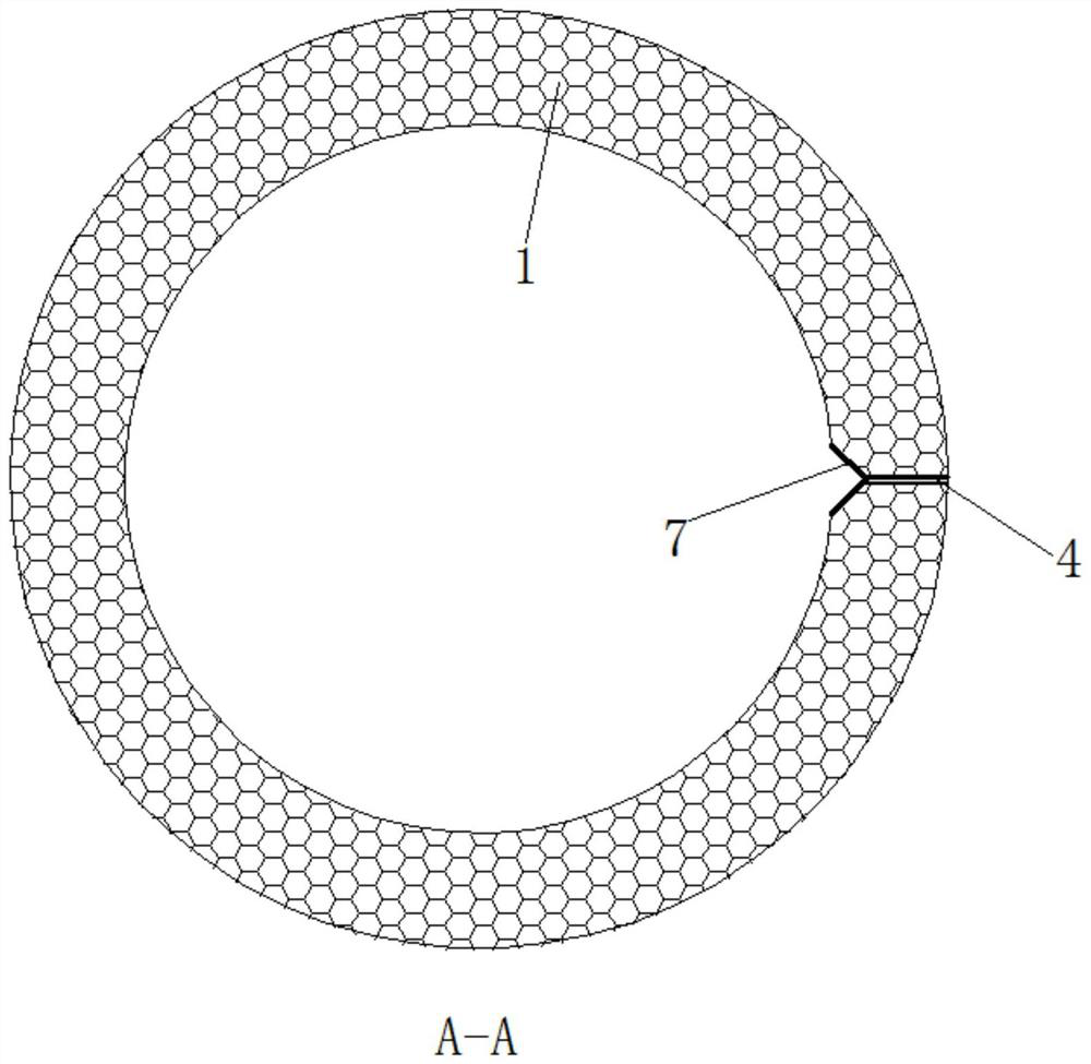
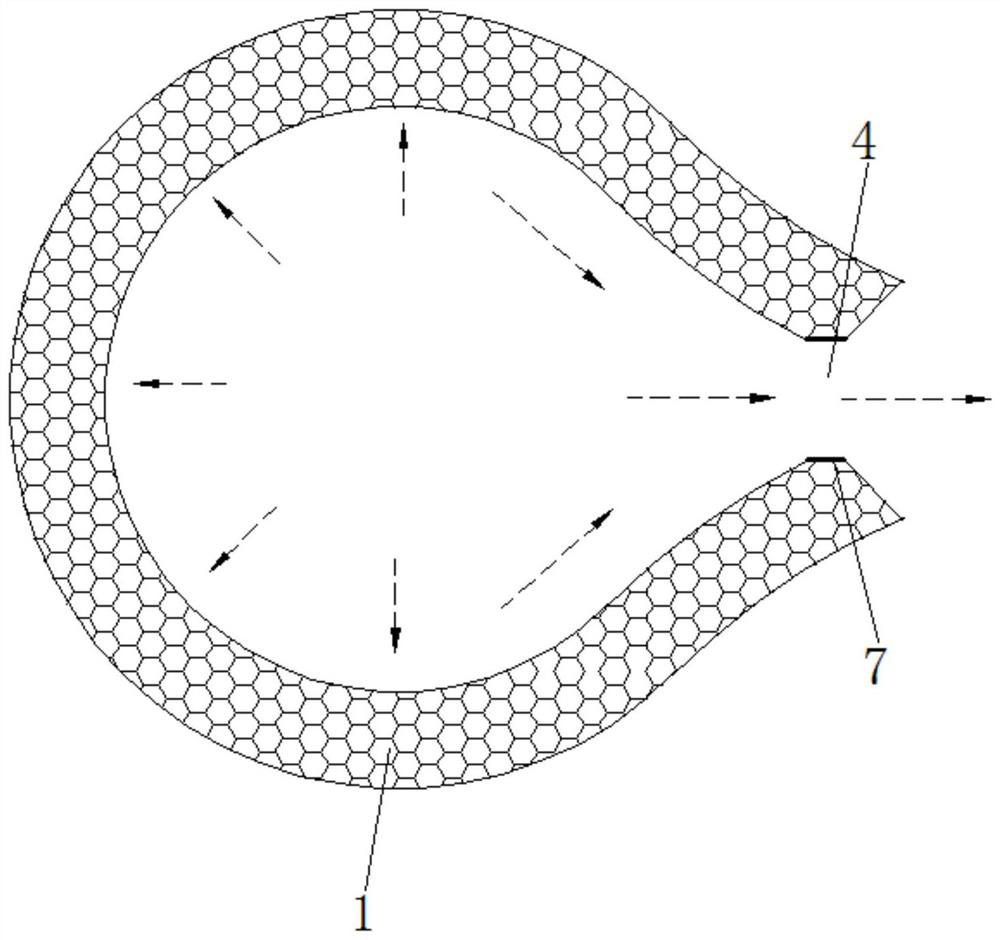
[0022] This embodiment relates to a novel anti-reflux ureteral stent, such as Figure 1-4 As shown, it includes: a hollow tube body 1 , a bladder segment 2 , a renal pelvis segment 3 , and a drainage incision 4 .

[0023] Specifically, the hollow pipe body 1 can undergo elastic deformation. The bladder segment 2 is arranged at one end of the hollow tube body 1 and crimped. When the ureteral stent is used, the bladder segment 2 is placed in the bladder. The renal pelvis segment 3 is arranged at the other en...


PUM


Abstract

The invention discloses a novel anti-backflow ureteral stent, and relates to the technical field of medical products. The novel anti-backflow ureteral stent comprises a hollow tube body which can elastically deform, a bladder section, a pelvis section and a urine discharge cut, wherein the bladder section is arranged at one end of the hollow tube body and curled, and is placed in a bladder duringuse; the pelvis section is arranged at the other end of the hollow tube body and curled, is placed in the renal pelvis during use; and, the urine discharge cut is arranged on the side, close to the bladder section, of the hollow tube body, and / or, arranged on the bladder section, and is used for automatically opening for urine discharge or closing to prevent backflow of urine according to pressurein the bladder and the hollow tube body; and when the ureteral stent is used, the urine discharge cut is placed in the bladder. According to the ureteral stent employing the technical scheme, the urine discharge cut is arranged on the hollow tube body or the bladder section, and opening or closing of the urine discharge cut is realized by utilizing the internal and external pressure difference ofthe hollow tube body and the bladder section, thereby achieving the anti-backflow effect; and the novel anti-backflow ureteral stent has the advantages of a simple structure, an ingenious design anda good anti-backflow effect.

Description

technical field [0001] The invention relates to the technical field of medical products, in particular to a novel anti-reflux ureteral stent. Background technique [0002] Ureteral stents are widely used in urological surgery, and are commonly used in urological surgery to drain urine. After kidney stones, ureteral stones, kidney transplantation, hydronephrosis, kidney and ureteral tumor surgery, and ureteral strictures, ureteral stents are routinely placed to ensure urine drainage from the kidneys to the bladder and avoid ureteral strictures and urinary fistulas , and contribute to the discharge of stone fragments. [0003] In the prior art, the two ends of the ureteral stent are mainly curled into rings and double J tubes. Such a structure can prevent slippage, but there is still the problem of bladder urine backflow, and the reason for the urine backflow is mainly because the ureteral stent is A catheter capable of bidirectional drainage. After indwelling a double-J cat...

Claims


Application Information

Patent Timeline
Patent Type & Authority Applications(China)
IPC IPC(8): A61F2/82A61M25/00
CPCA61F2/82A61M25/0017A61M25/0021A61M25/0043A61M25/0075A61M2025/0078A61M27/008
Inventor 曾思达阳鑫
Owner 深圳市惠心诺科技有限公司
Learn More