Surgical nursing stretcher

A technology for stretchers and surgery, applied in stretchers, vehicle ambulance, stereotaxic surgical instruments, etc., can solve the problems of increasing the weight of the stretcher, occupying a large space, and inconvenient storage, and achieve the effect of excellent support performance

Inactive Publication Date: 2020-10-13
王东艳
View PDF6 Cites 1 Cited by
  • Summary
  • Abstract
  • Description
  • Claims
  • Application Information

AI Technical Summary

Problems solved by technology

[0005] 1. When the surgical nursing stretcher in the prior art is in use, the patient will be lifted onto the support pad of the stretcher, and then the stretcher will be lifted to carry the patient, and the heavy patient will increase the burden on the medical staff who lift the stretcher, so it is necessary to Adding rollers at the bottom of the lifting rod makes the stretcher easy to lift and move, but the stretcher with rollers takes up a lot of space and is inconvenient for storage. Therefore, a stretcher that is easy to move and does not occupy storage space is needed. For this reason, we propose A kind of surgical nursing stretcher
[0006] 2. Most of the simple surgical nursing stretchers in the prior art are stretchers composed of fabric support pads sleeved with lifting rods, and the bottom of this stretcher will have a support plate welded to the bottom end of the lifting rod for support, and a wider support plate will increase the weight of the stretcher. weight, and then increase the burden of medical staff to lift, for this reason, we propose a surgical nursing stretcher
[0007] 3. When the existing surgical nursing stretcher lifts the patient, the head of the unconscious patient will shake on the surface of the support pad. As the stretcher is lifted, the patient's neck may be damaged due to long-term shaking. , we propose a surgical nursing stretcher

Method used


Image

  • Surgical nursing stretcher
  • Surgical nursing stretcher
  • Surgical nursing stretcher

Examples


Embodiment Construction

[0027] In order to make the objectives, technical solutions and advantages of the present invention clearer, the present invention will be further described in detail below with reference to the accompanying drawings. Obviously, the described embodiments are only a part of the embodiments of the present invention, rather than all of them. Based on the embodiments of the present invention, all other embodiments obtained by those of ordinary skill in the art without creative work shall fall within the protection scope of the present invention.

[0028] The following will combine Figure 1~Figure 4 The surgical nursing stretcher according to the embodiment of the present invention will be described in detail.

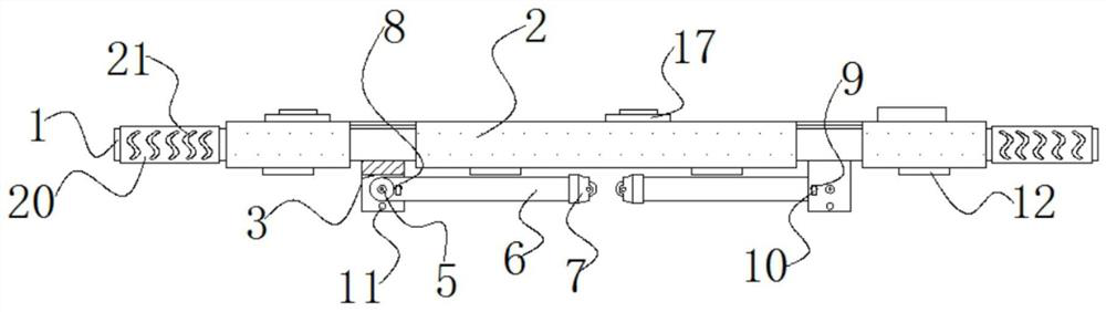
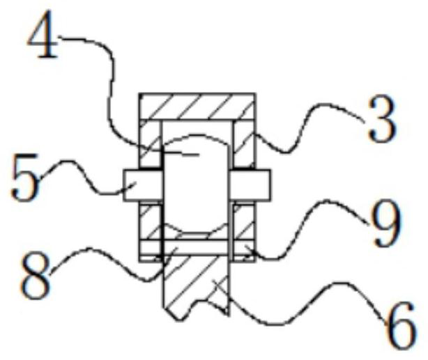
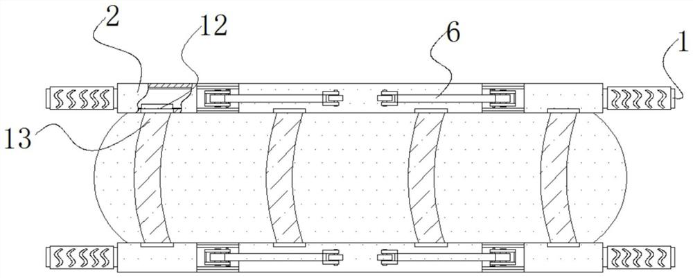
[0029] reference Figure 1-4 As shown, a surgical nursing stretcher provided by an embodiment of the present invention includes a lifting rod 1, a support pad 2 is sleeved on the outside of the lifting rod 1, and a base 3 is welded on the surface of the lifting rod 1 at the bot...


PUM


Abstract

The invention discloses a surgical nursing stretcher, and belongs to the technical field of surgical nursing medical device. The surgical nursing stretcher comprises lifting rods, a supporting pad sleeves the outer side of each lifting rod, a base is welded to the surface of each lifting rod at the bottom of the supporting pad, a rotating wheel is rotatably connected in the base, and movable boltsat two ends of the rotating wheel penetrate through the outer walls of two ends of the base; a pin hole B penetrates through the surface of a base, parallel to the side, of the movable bolt, and a pin hole C penetrates through the surface of the base, vertical to the side, of the bottom of the movable bolt. Fixing plates are welded between the lifting rods, and four sets of arc-shaped bent platesare welded between the fixing plates of the lifting rods, the four sets of arc-shaped bent plates between the lifting rods can provide excellent supporting performance for the surgical nursing stretcher, compared with a large supporting plate, the thin arc-shaped bent plates can greatly reduce the overall weight of the surgical nursing stretcher while guaranteeing the supporting performance, andunder the condition that idler wheels cannot be used for moving, the lighter surgical nursing stretcher can reduce the stretcher load when the patient is lifted and carried.

Description

Technical field [0001] The invention relates to the technical field of surgical nursing medical equipment, in particular to a surgical nursing stretcher. Background technique [0002] The scoop stretcher is composed of two left and right aluminum alloy plates. When transporting the wounded, first place the wounded in a supine position, fix the neck, and then insert the left and right pieces of the stretcher into the back from the side of the wounded, and buckle them before carrying it. It is also called "Stoke Basket". There are two common types: aluminum alloy type; synthetic resin type; its shape is similar to its name, like a "boat". When transporting the trapped persons, the trapped persons are placed in a stretcher. The "protruding" edges of the stretcher and the front flat belt will "enclose" the trapped persons inside the stretcher. This will not cause the trapped persons to leave the stretcher due to the displacement of the stretcher (such as turning, shaking). Behind ...

Claims


Application Information

Patent Timeline
Patent Type & Authority Applications(China)
IPC IPC(8): A61G1/02A61G1/013A61G1/04A61G1/056A61B90/14
CPCA61G1/02A61G1/013A61G1/04A61G1/0562A61B90/14A61G2203/70
Inventor 王东艳张迪关祥敏李娜
Owner 王东艳
Why Eureka
Try Eureka