
Plate polishing paint spraying device for machining

A technology of mechanical processing and plate, which is applied in the field of plate grinding and spraying equipment for mechanical processing, can solve the problems of low degree of automation, unfavorable work efficiency, troublesome use, etc., and achieve the effect of high degree of automation, saving working time and short use time

Inactive Publication Date: 2020-10-13
范翠英
View PDF1 Cites 11 Cited by
  • Summary
  • Abstract
  • Description
  • Claims
  • Application Information

AI Technical Summary

Problems solved by technology

[0004] The existing board needs to be painted after being polished. This patent can only realize the grinding of the board. It has a single function and a low degree of automation.

Method used


Image

  • Plate polishing paint spraying device for machining
  • Plate polishing paint spraying device for machining
  • Plate polishing paint spraying device for machining

Examples


Embodiment 1

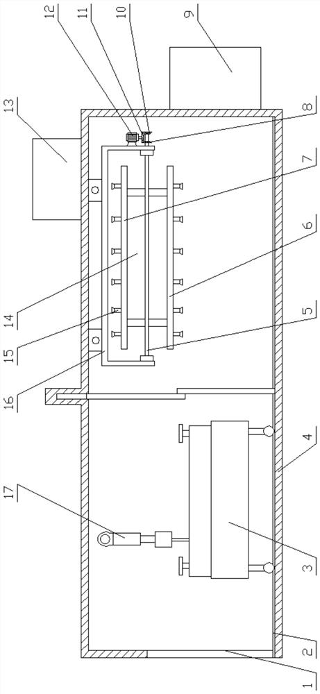
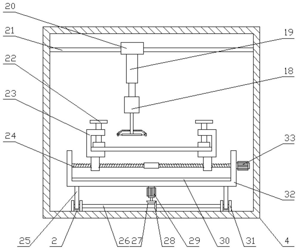
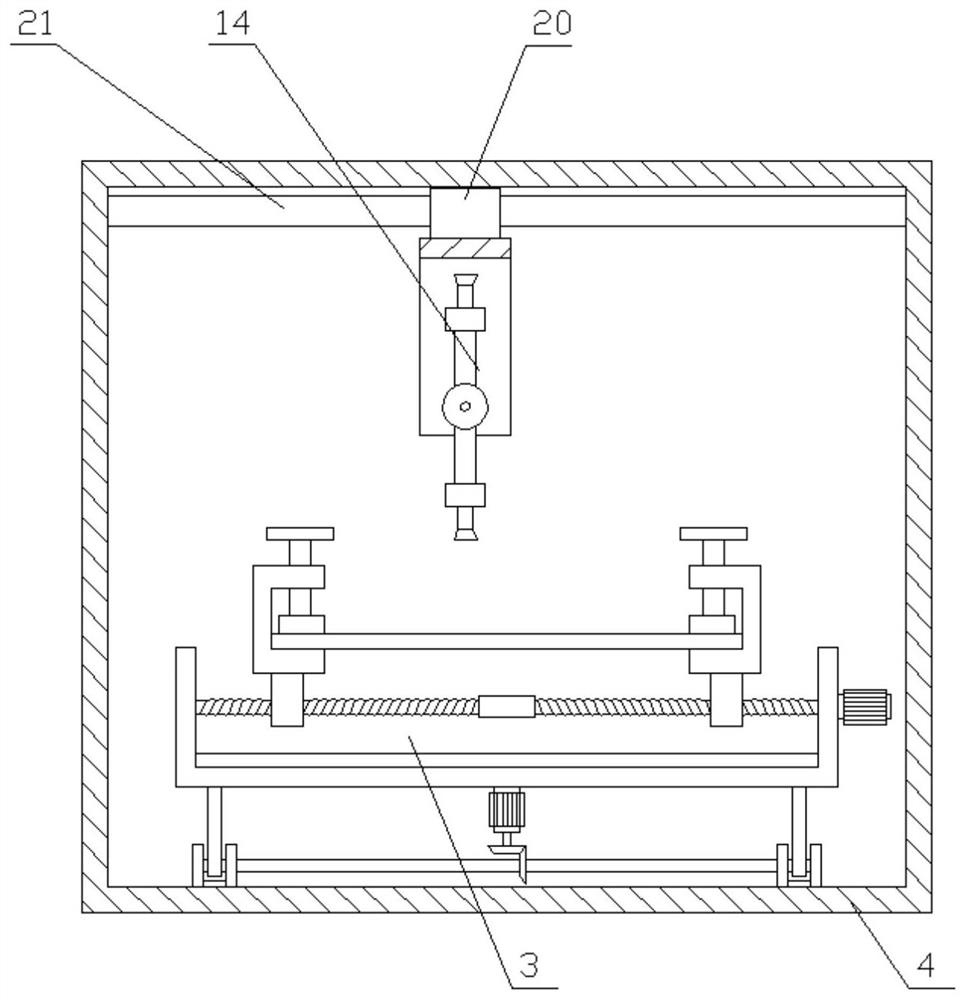
[0025] see Figure 1-2 , a kind of plate grinding and painting device for mechanical processing, comprising the first motor 12, the second motor 29, the third motor 33, telescopic cylinder 19, polishing machine 18, hot air blower 13 and casing 4, the output of the second motor 29 The end is fixedly connected with the third bevel gear 27, and the third bevel gear 27 meshes with the fourth bevel gear 28. The inlet 1 is arranged on the left side of the box body 4, and the hot air blower 13 is arranged on the upper side of the box body 4, and the right side of the box body 4 The paint box 9 is arranged on the side, the hot air blower 13 pipelines are connected to the hot air spray frame 7, and the pump pipeline is arranged in the paint box 9 to connect the paint spray frame 6, and the pump is used to pressurize the paint delivery, and the paint spray frame 6 and the hot air spray frame 7 are all Several nozzles 15 are set, which can increase the painting and drying area, and speed...

Embodiment 2

[0028] see figure 1 , The difference between this implementation and the above-mentioned embodiment 1 is that a protective door is provided in the middle of the box body 4, and the protective door is an electric push-close door, which can close the spray booth and prevent paint pollution.

[0029]The working principle of the present invention is: said a kind of plate grinding and painting device for mechanical processing, when using the device to polish and paint the plate, firstly according to the width of the plate, the third motor 33 is controlled to drive the threaded shaft 24 to rotate, supported by both sides The frame 23 clamps the side of the plate, then the upper surface of the plate is fixed by the compression bolt 22, the second motor 29 is controlled to rotate, the plate transport mechanism 3 is translated along the guide rail, and the grinding mechanism 17 is opened, controlled by the telescopic cylinder 19 The grinding disc 36 of the grinder 18 touches the surfac...


PUM


Abstract

The invention relates to the technical field of machining, and discloses a plate polishing paint spraying device for machining. The plate polishing paint spraying device comprises a first motor, a second motor, a third motor, a telescopic cylinder, a polishing machine, an air heater and a box body, wherein the output end of the second motor is fixedly connected with a third bevel gear, the third bevel gear is meshed with a fourth bevel gear, a plurality of rails are arranged on the lower side of the box body, a plate conveying mechanism is arranged on each rail, each plate conveying mechanismcomprises a supporting plate frame, a threaded shaft is rotatably connected with the upper side of each supporting plate frame, the threaded shafts are in threaded connection with a plurality of supporting frames, threads of the threaded shafts are symmetrically distributed about the center of the supporting frames, pressing bolts are arranged on the upper sides of the supporting frames, and a plurality of sliding rails are arranged on the upper side of the interior of the box body. The plate polishing paint spraying device is simple in structure, can realize polishing, paint spraying and paint drying processes of the plate, is high in automation degree, and high in grinding, paint spraying and paint drying efficiency, short in use time, capable of saving working time, and low in manufacturing cost, and has the usable value in the technical field of machining.

Description

technical field [0001] The invention relates to the technical field of mechanical processing, in particular to a plate grinding and painting device for mechanical processing. Background technique [0002] The machining process is the step of manufacturing and processing workpieces or parts. The process of directly changing the shape, size and surface quality of the blank to make it a part is called the machining process. Grinding is a common process in machining. Craft means. [0003] A grinding device for plate processing is disclosed in Chinese Patent Publication No. CN210413829U, which includes a bottom plate, a vertical plate is fixedly connected to the left side of the top of the bottom plate, and a horizontal plate is fixedly connected to the top of the right side of the vertical plate. A cylinder is fixedly connected to the top of the horizontal plate, and a bottom end of the cylinder passes through the horizontal plate and extends below it to be fixedly connected to...

Claims


Application Information

Patent Timeline
Patent Type & Authority Applications(China)
IPC IPC(8): B05B13/02B05B16/20B05B9/04B05D3/04B24B19/00B24B55/06
CPCB05B9/0403B05B13/0278B05D3/0413B24B19/00B24B55/06B05B16/20
Inventor 范翠英
Owner 范翠英
Learn More