Snow crushing resisting bus station platform

A bus and platform technology, applied in snow traps, special buildings, roofs, etc., can solve problems such as platform collapse and crushing, and achieve the effect of avoiding collapse

Inactive Publication Date: 2020-10-13
李会军
9 Cites 0 Cited by

AI-Extracted Technical Summary

Problems solved by technology

[0006] In view of this, the object of the present invention is to provide a snow pressure-resistant bus platform to solve...

Abstract

The invention relates to a snow crushing resisting bus station platform which comprises a ceiling and supporting pillars arranged at the bottom of the ceiling. The snow crushing resisting bus stationplatform further comprises a cleaning assembly used for removing accumulated snow on the ceiling. The cleaning assembly comprises a heat transfer shell arranged on the top of the ceiling, an electricheating wire arranged in the heat transfer shell and a snow shoveling mechanism used for shoveling accumulated snow. By means of the snow crushing resisting bus station platform, due to the cooperative use of the heat transfer shell, the electric heating wire, an electric push rod, a fixing block and a snow pushing shovel, when the strong snowfall weather exists, the electric heating wire begins to work, and the purpose of high-temperature snow melting is achieved. According to the technical scheme, due to the coherent and compact structure, the purpose of high-temperature melting of the accumulated snow is achieved, in addition, the purpose of accumulated snow pushing and sweeping is achieved, and therefore the accumulated snow on the top of the ceiling can be removed in two directions, and the phenomenon that too much snow is accumulated on the top of the ceiling, and the ceiling is collapsed and inclined is avoided effectively.

Application Domain

Special buildingSnow traps +1

Technology Topic

Electric heatingSnowpack +5

Image

  • Snow crushing resisting bus station platform
  • Snow crushing resisting bus station platform
  • Snow crushing resisting bus station platform

Examples

  • Experimental program(1)

Example Embodiment

[0028] In order to make the purposes, technical solutions and advantages of the embodiments of the present invention clearer, the technical solutions in the embodiments of the present invention will be clearly and completely described below with reference to the accompanying drawings in the embodiments of the present invention. Obviously, the described embodiments These are some embodiments of the present invention, but not all embodiments. The components of the embodiments of the invention generally described and illustrated in the drawings herein may be arranged and designed in a variety of different configurations.
[0029] Thus, the following detailed description of the embodiments of the invention provided in the accompanying drawings is not intended to limit the scope of the invention as claimed, but is merely representative of selected embodiments of the invention. Based on the embodiments of the present invention, all other embodiments obtained by those of ordinary skill in the art without creative efforts shall fall within the protection scope of the present invention.
[0030] It should be noted that like numerals and letters refer to like items in the following figures, so once an item is defined in one figure, it does not require further definition and explanation in subsequent figures.
[0031] In the above description of the present invention, it should be noted that the orientation or positional relationship indicated by the terms "one side", "the other side", etc. is based on the orientation or positional relationship shown in the drawings, or when the product of the invention is used. The usual orientation or positional relationship is only for the convenience of describing the present invention and simplifying the description, rather than indicating or implying that the referred device or element must have a specific orientation, be constructed and operated in a specific orientation, and therefore should not be construed as a Invention limitations. Furthermore, the terms "first", "second", etc. are only used to differentiate the description and should not be construed to indicate or imply relative importance.
[0032] Furthermore, terms such as the term "identical" do not imply that the components are required to be absolutely identical, but minor differences may exist. The term "perpendicular" simply means that the positional relationship between components is more vertical than "parallel", and does not mean that the structure must be completely vertical, but may be slightly inclined.
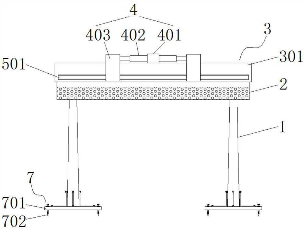
[0033] see Figure 1-5 , the present invention provides a technical solution: a snow pressure-resistant bus stop, comprising a ceiling 2 and a support column 1 arranged at the bottom of the ceiling, and also includes a cleaning component for cleaning the snow on the ceiling;
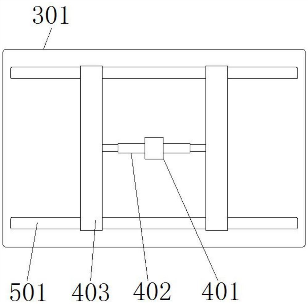
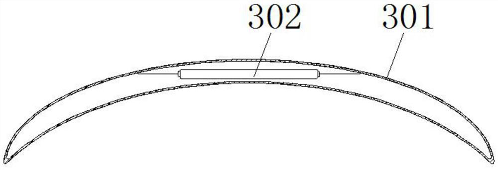
[0034] The cleaning assembly 3 includes a heat transfer housing 301 arranged on the top of the ceiling, an electric heating wire 302 arranged inside the heat transfer housing, and a snow ploughing mechanism 4 for removing snow, and the interior of the heat transfer housing is a hollow structure , the electric heating wire can release heat inside the heat transfer shell, so that a heat storage cavity is formed inside the heat transfer shell to conduct heat conduction to the snow on the top of the ceiling, so as to achieve the snow melting effect. The heating wire starts to work through the external power supply of the wire, and the heat generated can store the heat energy inside the heat transfer shell. At this time, the heat energy can conduct heat conduction to the snow on the top of the heat transfer shell, so as to achieve the purpose of high temperature snow melting;
[0035] The snow ploughing mechanism 4 includes a fixed block 401 arranged at the top of the heat transfer shell near the middle position, an electric push rod 402 arranged on both sides of the fixed block, and a snow shovel 403 respectively arranged at the output ends of the two electric push rods. When the rod reciprocates and expands, it can drive the snow shovel to push and sweep the snow. The model of the electric push rod can be JF-TGA-F electric push rod. The rod starts to work through the external power supply of the wire, and its reciprocating telescopic motion can drive the snow shovel to push the snow away, and further prevent the snow from accumulating on the top of the heat transfer shell. Snow, two methods of clearing snow, can ensure that the top of the roof will not collapse or collapse due to excessive snow accumulation;
[0036] The inner side of the ceiling is provided with an interlayer partition 6 along the direction of the inner wall. The space between the interlayer partition and the inner wall of the ceiling constitutes an air flow space. The two sides of the ceiling are provided with air flow holes that communicate with the air flow space. The air outside the ceiling can pass through the ceiling. The airflow holes on one side flow into the airflow space, and then flow out through the airflow holes on the other side of the ceiling, thereby reducing the pressure of the outside wind on the ceiling. When encountering strong winds, the airflow can flow into the airflow space through the airflow holes on the ceiling side. inside, and then discharged through the airflow hole on the other side of the ceiling, thereby reducing the pressure of strong airflow on the side of the ceiling in strong windy weather, and enhancing the stability of the tool.
[0037]In the present invention, it also includes a guide member 5 for driving the snow pusher to guide the snow pusher, where the guide member can be used to prevent the snow pusher from shifting and shaking too much during the working process.
[0038] In the present invention, the guide member 5 includes a chute channel 501 and sliders 502 arranged at the ends of both sides of the snow shovel. One side of the chute channel is provided with a sliding channel that can facilitate the sliding of the slider, and the two sliding channels are opposite to each other. Set on both sides of the ceiling, when the slider slides in the inner side of the chute, it can drive the snow shovel to push the snow in a constant direction. So as to ensure the stability of the snow shovel in the sliding process.
[0039] In the present invention, the diameter of the cross section from the top to the bottom of the support column 1 is gradually increased, so that the support column is in the shape of a cone, and the structural shape of the support column is further defined here. Enhance the stability of this tool.
[0040] In the present invention: a reinforcement component 7 for enhancing the stability of the ceiling is also included, and the stability of the tool is further enhanced by the reinforcement component here.
[0041] In the present invention, the reinforcement assembly 7 includes a support plate 701 and a threaded bolt 702 that are fixedly connected to the bottom of the support column. The top of the support plate is provided with a threaded hole, and the threaded bolt can be screwed on the inner side of the threaded hole and extend below the installation ground. , to fix the support plate, where the user can first stand the support plate upright on the ground, and install it by welding or riveting, and then push the threaded bolts deep below the installation ground, thereby increasing the tool and the The contact area between the ground, so as to achieve the purpose of enhancing the stability of the tool.
[0042] In the present invention, the reinforcement assembly 7 further includes a support member 8, and the support members are provided with four, and the four ends are in an encircling shape to the support column. The card slot block 802 on the top side of the support plate, one side of the card slot block is provided with a card slot that can facilitate the locking of the L-shaped support plate, the L-shaped support plate is closely attached to the side wall of the support column and the top of the support rod, and the L-shaped support plate The support plate is located inside the slot to form a reinforced connection to the support column and the support plate. The top of the slot block is provided with a first threaded hole extending to the inside of the slot, and the surfaces of both ends of the L-shaped support plate are provided with a second thread. The outer side of the slot block is provided with a fixing bolt 9. The fixing bolt is threaded through the first threaded hole and the second threaded hole in turn to form a threaded connection. Here, the L-shaped support plate is further placed inside the slot, and passed through The fixed threaded bolts are tightened, and the support column is surrounded by the four-end fixing method. Even if the support column is subjected to impact force from any direction of the four ends, the L-shaped support plate will pass through the groove block for the first time. Connectivity, generate reaction force, can dissolve the external impact force borne by the support column, and enhance the stability of the tool.
[0043] Finally, it should be noted that the above embodiments are only used to illustrate the technical solutions of the present invention and not to limit them. Although the present invention has been described in detail with reference to the preferred embodiments, those of ordinary skill in the art should understand that the technical solutions of the present invention can be Modifications or equivalent replacements without departing from the spirit and scope of the technical solutions of the present invention should be included in the scope of the claims of the present invention.

PUM

no PUM

Description & Claims & Application Information

We can also present the details of the Description, Claims and Application information to help users get a comprehensive understanding of the technical details of the patent, such as background art, summary of invention, brief description of drawings, description of embodiments, and other original content. On the other hand, users can also determine the specific scope of protection of the technology through the list of claims; as well as understand the changes in the life cycle of the technology with the presentation of the patent timeline. Login to view more.

Similar technology patents

Cigarette filter tip

InactiveCN102754919APrevent collapseSmooth ventilationTobacco smoke filtersCigarette filterEngineering
Owner:许继东 +2

Vertical vibrating pre-forming production process for large-diameter reinforced concrete drainage pipe

InactiveCN102528925APrevent collapseSave coal energyShaping reinforcementsSlagRebar
Owner:马鞍山钢铁建设集团有限公司

Classification and recommendation of technical efficacy words

Why Eureka
Try Eureka