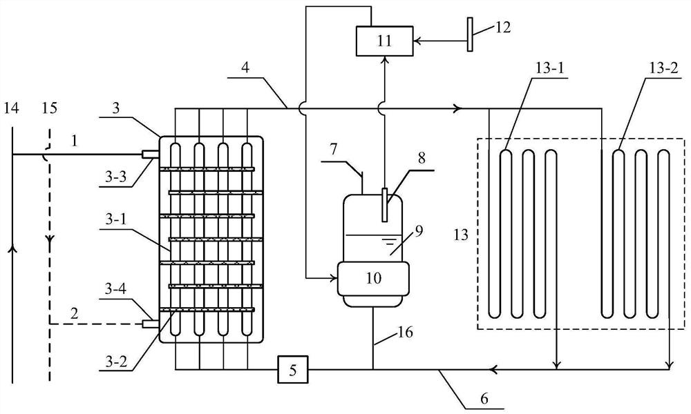
Efficient indoor heating system for capillary pump
A heating system and capillary pump technology, which is applied in hot water central heating system, heating system, high-efficiency regulation technology, etc. The effect of good operation reliability and reduction of total operating energy consumption
- Summary
- Abstract
- Description
- Claims
- Application Information
AI Technical Summary
Problems solved by technology
Method used
Image
Examples
Embodiment 1
[0040] Adopting this system can reduce the power consumption of the circulating pumps in the primary and secondary networks of the heating system.
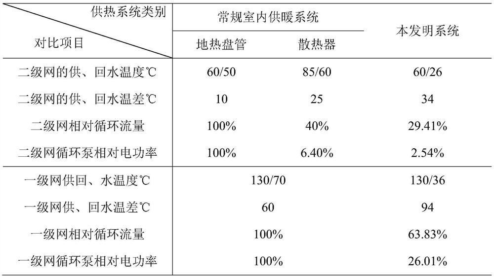
[0041] Table 1
[0042]
[0043] Table 1 shows the energy consumption comparison of primary and secondary network circulating pumps of different indoor heating systems. It can be seen from Table 1 that compared with the conventional indoor heating system using geothermal coils or radiators, the designed return water temperature of the secondary network of the system of the present invention is lower (only 26°C), and the temperature difference between the supply and return water of the secondary network increases. Large, under the same heat load conditions, the relative circulation flow of the secondary network is only 29.41% of that of the conventional geothermal coil indoor heating system. 2.54%.
[0044] In addition, the lower return water temperature of the secondary network can reduce the return water temperature of the c...
Embodiment 2
[0046] The adoption of this system can improve the recycling rate of low-grade waste heat energy and reduce the total operating energy consumption of the heating system.
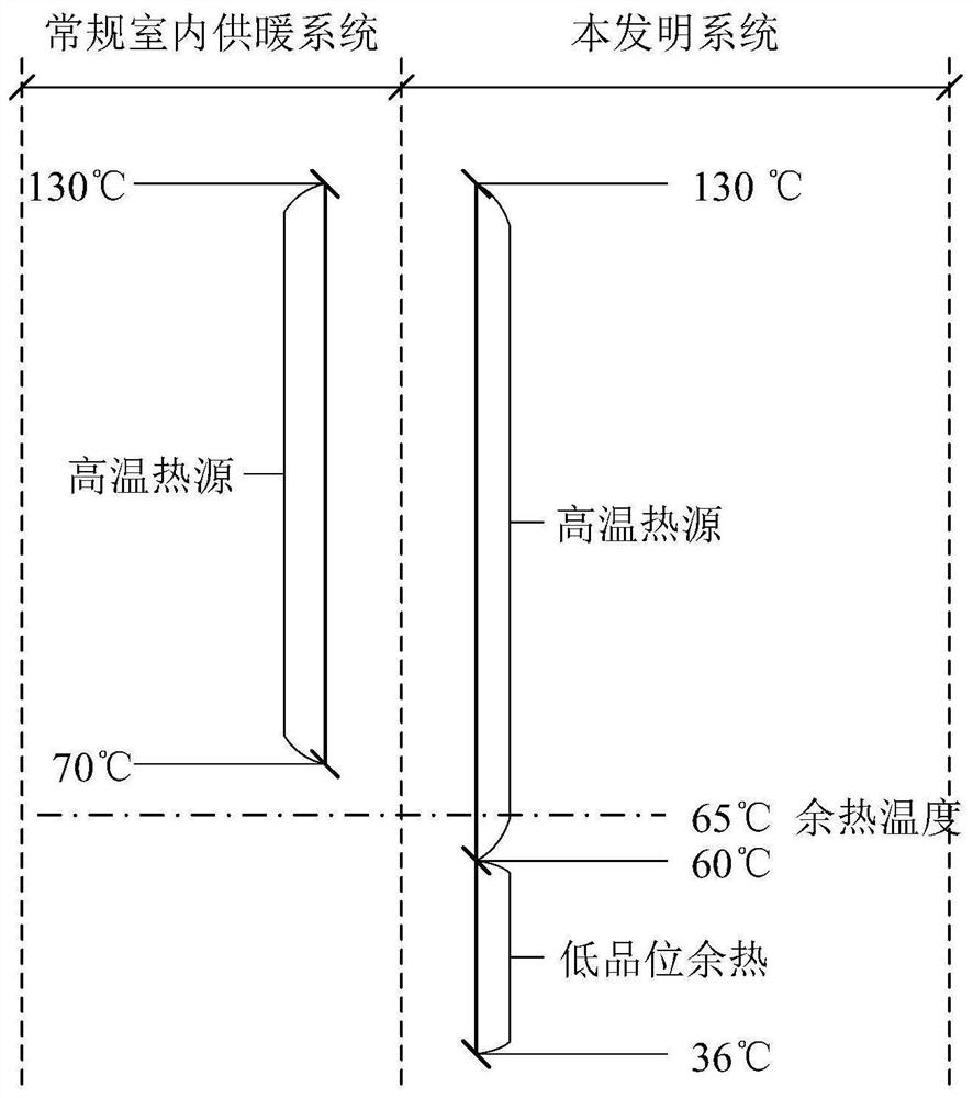
[0047] If there is a low-grade waste heat energy with a temperature of 65°C and a stable supply, the total amount is huge. When the indirect connection heating system is adopted (the end heat dissipation equipment is a geothermal coil or radiator), since the design return water temperature (70°C) of the primary network is higher than the temperature of the low-grade waste heat, this part of the waste heat resource cannot be utilized; however , when the system of the present invention is adopted, the design return water temperature of the primary network can be reduced to 36°C, and the low-temperature waste heat of 65°C can be effectively utilized.
[0048] Assuming that the heat medium can be heated to 60°C after the heat exchange with the low-temperature waste heat source, and then enter the high-temperatur...
Embodiment 3
[0052] This system can directly use low-grade waste heat for heating, saving fossil fuel consumption.
[0053] Assume that the temperature of a low-grade waste heat energy is 50°C, the supply is stable, and the total amount is huge. When the direct connection heating system is adopted, since the return water temperature (50, 60°C) of the terminal heat dissipation equipment (geothermal coil, radiator) is higher than the temperature of low-grade waste heat, this part of waste heat resources cannot be effectively utilized.
[0054] When the system of the present invention is adopted, the return water temperature of the terminal heat dissipation equipment can be reduced to 26°C, thereby meeting the conditions for direct utilization of such low-grade waste heat. For a heating system with a building area of 100,000 square meters, the total amount of low-grade waste heat recovered and utilized throughout the heating season is (assuming that the system operates for 150 days in the h...
PUM
 Abstract
Description
Claims
Application Information
 - R&D
- Intellectual Property
- Life Sciences
- Materials
- Tech Scout
- Unparalleled Data Quality
- Higher Quality Content
- 60% Fewer Hallucinations
Browse by: Latest US Patents, China's latest patents, Technical Efficacy Thesaurus, Application Domain, Technology Topic, Popular Technical Reports.
© 2025 PatSnap. All rights reserved.Legal|Privacy policy|Modern Slavery Act Transparency Statement|Sitemap|About US| Contact US: help@patsnap.com


