Small thermal gas mass flow meter

A gas mass flow and thermal technology, applied in indirect mass flowmeters, mass flow measurement devices, etc., can solve problems such as difficulty in application, and achieve the effects of simple structure, convenient use and operation, and increased analysis functions

Pending Publication Date: 2020-10-13
张树生
View PDF0 Cites 0 Cited by
  • Summary
  • Abstract
  • Description
  • Claims
  • Application Information

AI Technical Summary

Problems solved by technology

[0005] The purpose of the present invention is to provide a small thermal gas mass flowmeter for the technical defects of the prior art, so as to solve the technical problem in the prior art that the conventional pipe section thermal gas mass flowmeter is difficult to apply to the caliber below DN20

Method used


Image

  • Small thermal gas mass flow meter
  • Small thermal gas mass flow meter
  • Small thermal gas mass flow meter

Examples


Embodiment 1

[0033] A small thermal gas mass flowmeter, including a housing, a circuit assembly, and a sensor assembly;

[0034] The above-mentioned circuit device includes a speed sensor, a temperature sensor, a signal acquisition module, a signal processing control module, a button module, a display module, a communication module, an output module, a power detection module, a sensor power module, a power module and a battery;

[0035] The speed measuring sensor and the temperature measuring sensor are respectively electrically connected to the signals of the signal acquisition module; the signal acquisition module, the button module, the display module, the communication module, the output module, the power detection module, and the sensor power module are respectively electrically connected to the signals of the signal processing control module; The communication module is electrically connected with the signal processing control module for bidirectional signals; the power supply module ...

Embodiment 2

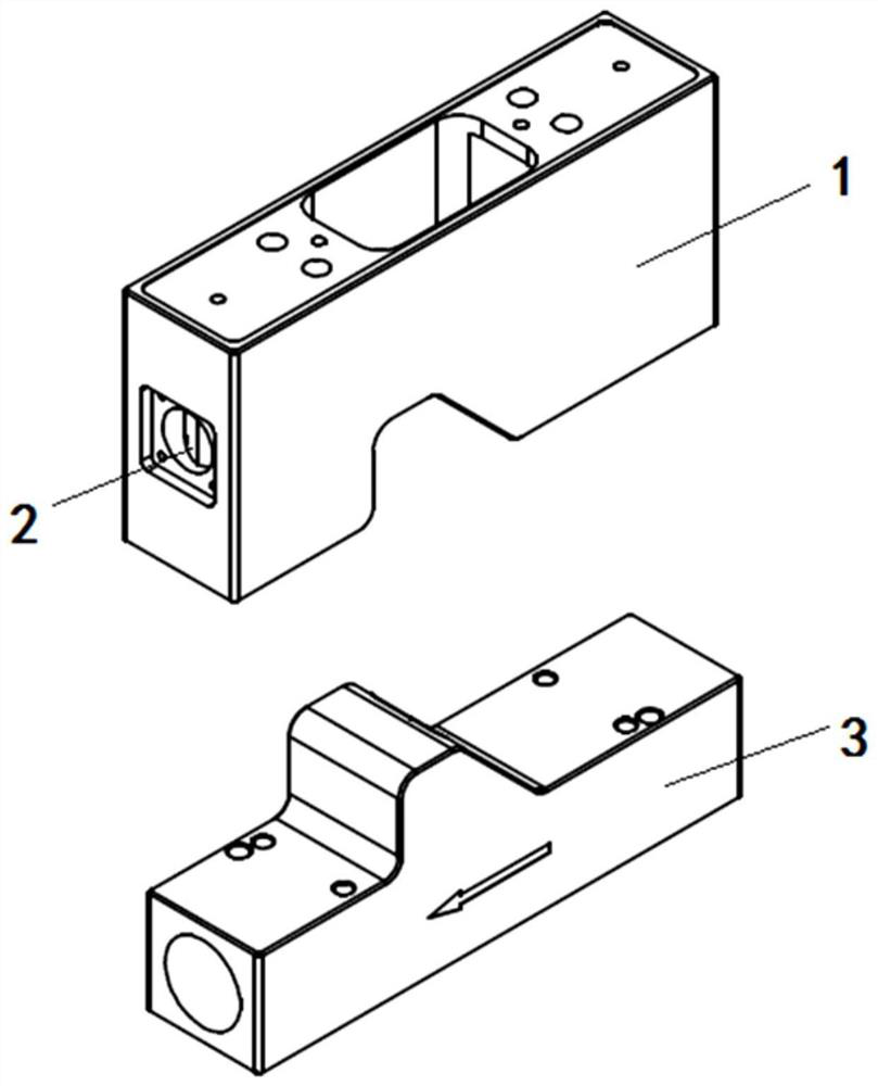
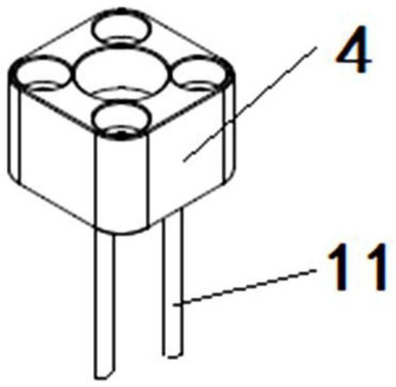
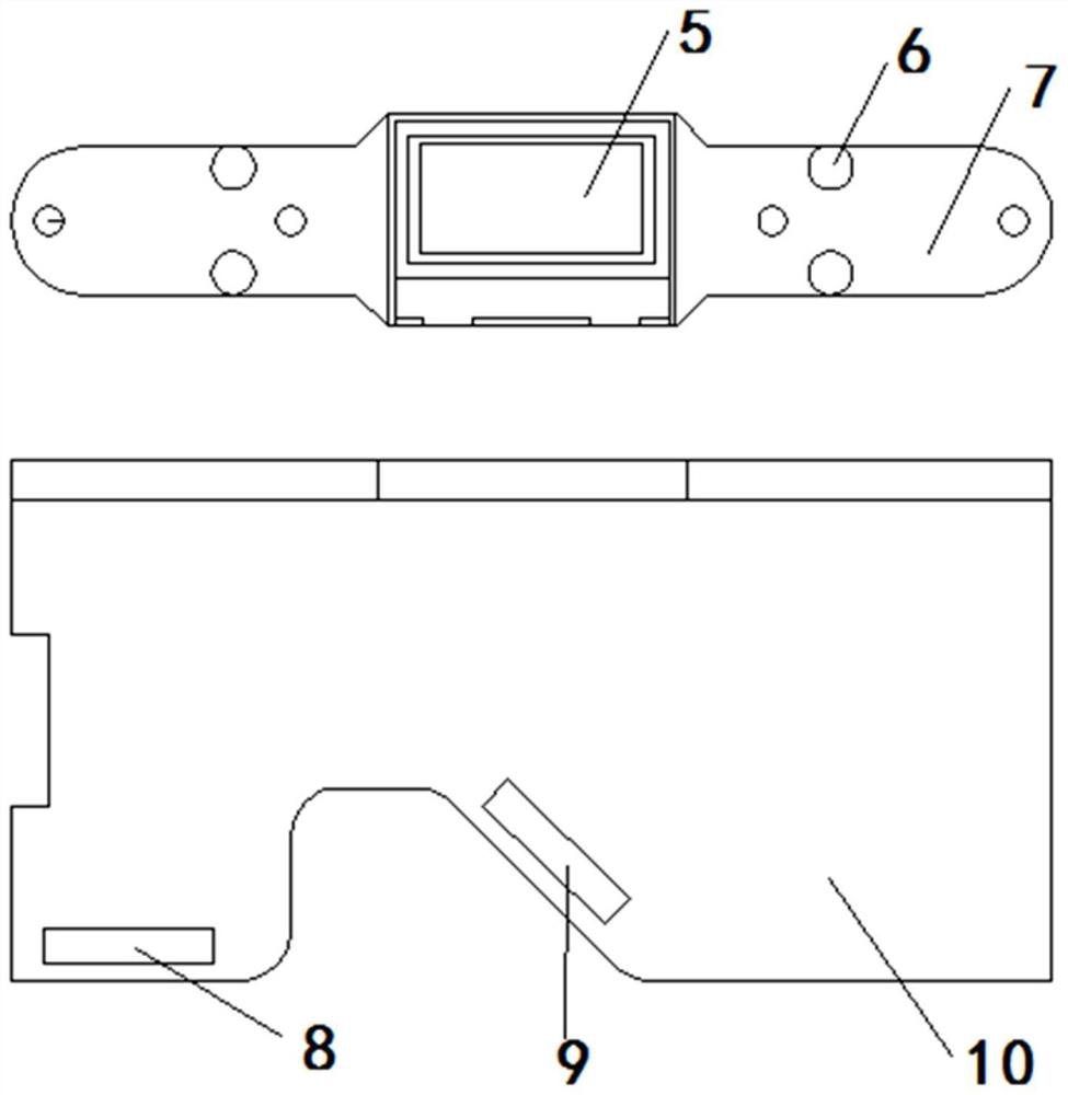
[0040] Small thermal gas mass flow meters, such as Figure 1~4 As shown, it is mainly composed of a casing, a circuit device, and a sensor device.

[0041] The shell is mainly composed of an upper shell 1 and a lower shell 3 .

[0042] The circuit device is mainly composed of a power module 12, a sensor power module 13, a signal acquisition module 16, a signal processing control module 17, a button module 18, a display module 19, a communication module 20, an output module 21, a power detection module 22, and a power supply 23.

[0043] The display module 19 is used for real-time display of measured values, inquiry of stored values ​​of measured values, indication of working status and prompt of faults.

[0044] The button module 18 is used for parameter setting and data query date setting.

[0045] The signal acquisition module 16 receives the output signals of each sensor, filters and amplifies the signals, converts them into voltage signals, and transmits them to the sign...


PUM


Abstract

The invention provides a small thermal gas mass flow meter. According to the small thermal gas mass flow meter, a housing upper shell and a housing lower shell are mutually buckled to form a completehousing, and an input and output aviation socket interface is arranged at the side end of the complete housing; a sensor packaging outer sleeve is arranged outside the sensor, and the lower end of thesensor packaging outer sleeve is fixedly connected with a sensor probe; a display and a button are respectively arranged on a base plate, and the base plate is fixedly connected to the top part of the housing upper shell; a main control board is respectively provided with an input/output connecting port and a sensor connecting port, the main control board is arranged in the complete housing, thesensor is connected with the sensor connecting port, and the sensor is arranged on the housing lower shell by means of the sensor packaging outer sleeve. The small thermal gas mass flow meter can be suitable for the caliber less than DN20, is simple in structure, is less affected by the change of a gas flow state, is high in measurement precision, is not limited by field conditions, can display and store measurement data in real time, and is convenient in use and operation.

Description

technical field [0001] The invention relates to the technical field of gas mass flow meters, in particular to a small thermal gas mass flow meter. Background technique [0002] Thermal flowmeter is a flow meter designed based on the principle of thermal diffusion. That is, when the fluid flows through the heating object, the heat loss of the heating object is proportional to the flow rate of the fluid. This type of flowmeter is generally equipped with two sets of resistive temperature sensors, one is used as a heat source, and the other is used as a heat source. To measure the fluid temperature, when the fluid flows, the temperature difference between the two has a linear relationship with the flow rate, and then through the microelectronic control technology, this relationship is converted into a linear output of the measured flow signal. [0003] Thermal gas mass flowmeters are divided into two types according to their installation methods: insertion type and pipe section...

Claims


Application Information

Patent Timeline
Patent Type & Authority Applications(China)
IPC IPC(8): G01F1/86
CPCG01F1/86
Inventor 张树生陈永峰
Owner 张树生
Why Eureka
Try Eureka