
Control method and device for deep-energy-level transient spectrum trigger signal, and storage medium

A technology of triggering signal and control method, applied in the field of testing, can solve the problems of difficulty in eliminating interference signals, affecting the accuracy of results, and difficult to eliminate interference signals, so as to improve reliability, reduce weak interference, and eliminate high-frequency transient changes. the effect of interference

Active Publication Date: 2020-10-13
HARBIN INST OF TECH
View PDF9 Cites 0 Cited by
  • Summary
  • Abstract
  • Description
  • Claims
  • Application Information

AI Technical Summary

Problems solved by technology

On the one hand, in this test method, since the interference signal is random, it is difficult to take corresponding measures to eliminate the interference signal; on the other hand, the interference will propagate to other parts of the system through conduction and radiation, and the The weak voltage measurement and weak current measurement of the
Therefore, in the existing deep-level transient spectrum test methods, the means of triggering signals often introduces a variety of interference signals, and such interference signals are difficult to eliminate, which greatly affects the accuracy of the final results

Method used


Image

  • Control method and device for deep-energy-level transient spectrum trigger signal, and storage medium
  • Control method and device for deep-energy-level transient spectrum trigger signal, and storage medium
  • Control method and device for deep-energy-level transient spectrum trigger signal, and storage medium

Examples


Embodiment Construction

[0049] Embodiments according to the present invention will be described in detail below with reference to the drawings. When the description refers to the drawings, the same reference numerals in different drawings indicate the same or similar elements unless otherwise indicated. It should be noted that the implementations described in the following exemplary embodiments do not represent all implementations of the present invention. They are merely examples of apparatus and methods consistent with certain aspects of the present disclosure as recited in the claims, and the scope of the present invention is not limited thereto. On the premise of no contradiction, the features in the various embodiments of the present invention can be combined with each other.

[0050] In addition, the terms "first" and "second" are used for descriptive purposes only, and cannot be interpreted as indicating or implying relative importance or implicitly specifying the quantity of indicated technic...


PUM


Abstract

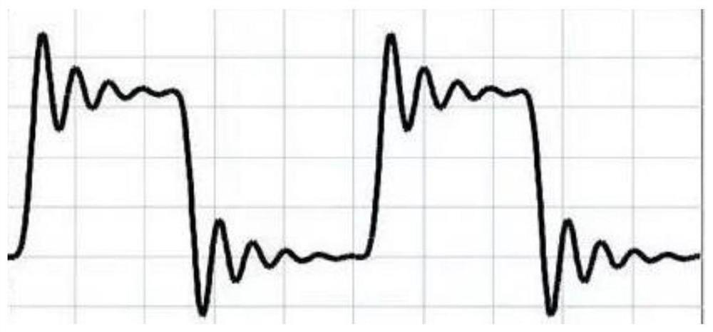
The invention provides a control method and device for a deep-energy-level transient spectrum trigger signal, and a storage medium, and relates to the technical field of testing. The method comprisesthe following steps: determining trigger signal curve data according to a preset duration, wherein the trigger signal curve data comprise a zero-voltage data segment, a transition curve data segment and a maintaining amplitude data segment, and the transition curve data segment forms a smooth rising edge curve or a falling edge curve and is used for achieving smooth transition between the zero-voltage data segment and the maintaining amplitude data segment; converting the trigger signal curve data into an analog signal; modulating the analog signal to form an injection voltage signal so as toinject the injection voltage signal into a tested device. A zero-voltage injection form is adopted, so that an injection pulse signal forms a rising edge and a falling edge of the signal in a zero-voltage edge piecewise exponential function waveform form, a sharp edge of the waveform is eliminated, and transient change high-frequency distortion of the waveform is eliminated, thereby ensuring the transient of triggering and reducing the interference of the system.

Description

technical field [0001] The present invention relates to the technical field of testing, in particular to a method, device and storage medium for controlling a deep-level transient spectrum trigger signal. Background technique [0002] Deep Level Transient Spectroscopy (DLTS) is an effective method to study the doping concentration, defect energy level and interface state (trapping interface) of semiconductors. To the bias voltage, and superimposed a periodic pulse voltage, under the action of the pulse, the electrons have a process of filling and releasing at the deep energy level, thereby forming a capacitive transient, and the deep energy can be determined through the information of the capacitive transient The spectral lines of the transient spectrum. [0003] In the existing deep-level transient spectrum test method, a DC power supply and a pulse switch are generally applied to the device under test, and a positive or negative voltage is superimposed on both ends of the...

Claims


Application Information

Patent Timeline
Patent Type & Authority Applications(China)
IPC IPC(8): G01R31/26G01R27/26G05B15/02
CPCG01R31/2607G01R31/2601G01R27/2605G05B15/02
Inventor 李兴冀杨剑群吕钢董尚利
Owner HARBIN INST OF TECH
Learn More