
Environment sensing system based on laser radar

A lidar and environmental perception technology, applied in the field of lidar-based environmental perception systems, can solve problems such as confusion, poor lighting conditions, and insufficient computing efficiency of far-infrared camera detection and tracking algorithms to be used in real time, to save computing resources. Effect

Pending Publication Date: 2020-10-13
苏州泛像汽车技术有限公司
View PDF0 Cites 3 Cited by
  • Summary
  • Abstract
  • Description
  • Claims
  • Application Information

AI Technical Summary

Problems solved by technology

[0003] At present, the problem of environmental perception of autonomous driving technology is that in the case of strong light, the camera will produce lens flares, and large shadows and other adverse lighting conditions will also have different effects on perception. For example, the vision system may confuse large shadows as Part of other objects, in addition, may need to add different visual cues (such as taillights, reflective road markings, etc.) or thermal imaging (far infrared) cameras to the current perception system to improve performance in low light conditions or at night, and even then, There is still no guarantee that there will be no obstacles that the system does not detect and track. At the same time, a large number of far-infrared camera detection and tracking algorithms are not computationally efficient enough for real-time use. Other perception systems try to solve the problem of light conditions by relying on prior information about the environment. However, the prior information is not static. If a new traffic light does not have prior information entered, it will cause trouble when the self-driving vehicle encounters it. Using lidar to overcome poor lighting conditions, this sensor does not Requires external light, so it can detect obstacles in low light and at night, so it can provide different advantages for better results in poor lighting conditions, but in this regard, extensive research is still needed to solve the remaining challenges

Method used


Image

  • Environment sensing system based on laser radar
  • Environment sensing system based on laser radar
  • Environment sensing system based on laser radar

Examples


Embodiment Construction

[0054] The following will clearly and completely describe the technical solutions in the embodiments of the present invention with reference to the accompanying drawings in the embodiments of the present invention. Obviously, the described embodiments are only some, not all, embodiments of the present invention. Based on the embodiments of the present invention, all other embodiments obtained by persons of ordinary skill in the art without making creative efforts belong to the protection scope of the present invention.

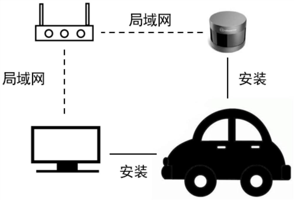
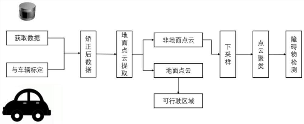
[0055] Such as Figure 1-2 As shown, the embodiment of the present invention provides a technical solution: a lidar-based environment perception system, including lidar, self-driving cars and computers, and the rigid connection between the lidar and the self-driving car, in order to obtain more road information ahead In this paper, the laser radar is generally installed in front of the car. The data between the laser radar and the computer is transmitted throu...


PUM


Abstract

The invention discloses an environment sensing system based on a laser radar. The environment sensing system comprises the laser radar, an automatic driving automobile calibration module, a ground point cloud extraction module, a point cloud data down-sampling module and a laser radar data point cloud clustering module. According to the environment sensing system based on the laser radar, the calibration between the laser radar data and the automatic driving automobile can be completed; a stable rotation translation matrix can be used, the algorithm difficulty is low, the development and maintenance cost is low, laser radar data down-sampling can be achieved, the algorithm has a very long history by using the stable algorithm, the algorithm reliability is fully proved by various experiments, and the development and maintenance cost is low.

Description

technical field [0001] The invention relates to the technical field of automobile engineering, in particular to an environment perception system based on laser radar. Background technique [0002] The United States is the country with the most in-depth research on autonomous vehicles. Its research on autonomous vehicles began in the 1970s and 1980s, and has been in a high-speed development stage since the 1980s. The DAPAR program of the US Department of Defense is extremely It has greatly promoted the development of self-driving cars and obtained a series of major research results. Domestic research on self-driving cars started in the 1980s, including the National University of Defense Technology, Nanjing University of Science and Technology, and Tsinghua University. Until 2003 The National University of Defense Technology and FAW Group Corporation jointly developed the automatic driving system for Hongqi cars, marking that my country's autopi The driving scheme is to use on-b...

Claims


Application Information

Patent Timeline
IPC IPC(8): G01S17/931G06K9/00G06K9/62
CPCG01S17/931G06V20/58G06F18/23
Inventor 高传宝徐江王长坤
Owner 苏州泛像汽车技术有限公司
Learn More