Antenatal care platform for pregnant woman
A technology for pregnant women and platforms, which is applied in the field of medical equipment, can solve problems such as waist injuries, and achieve the effects of convenient operation, guaranteed safety, and strong practicability
- Summary
- Abstract
- Description
- Claims
- Application Information
AI Technical Summary
Problems solved by technology
Method used
Image
Examples
Embodiment 1
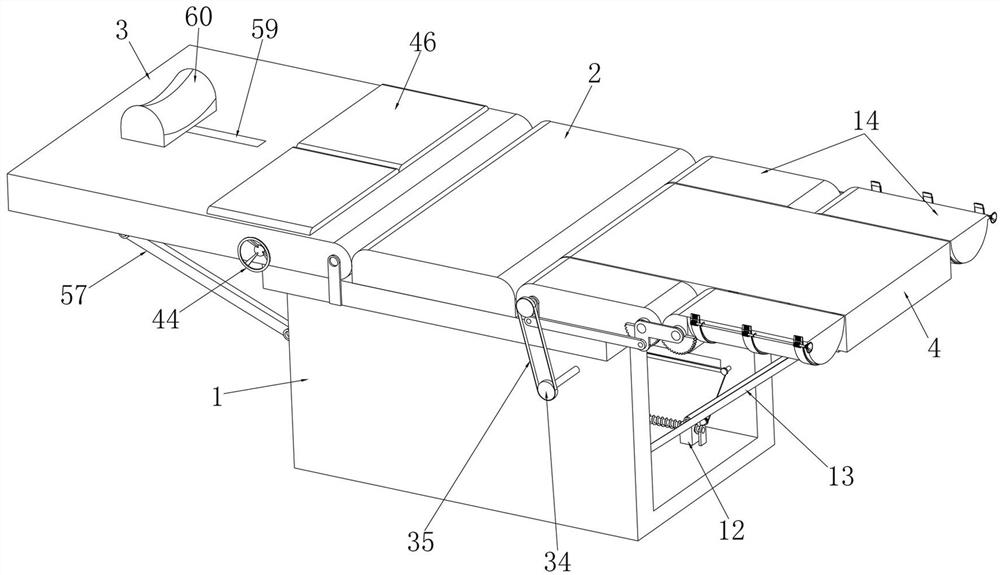
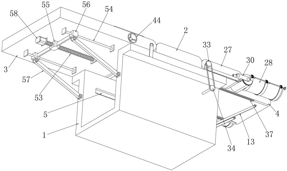
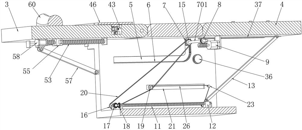
[0046] Embodiment 1, the present invention is an obstetric examination platform for pregnant women, including a base 1 with a hollow interior and a "U" shape. The cross section of the base 1 is "U" shaped, and the left and right sides and the top of the base 1 are open. 1 provides a fixed foundation for the follow-up structure, and it is characterized in that the buttocks bed board 2 is fixedly installed in the middle of the top surface of the base 1, the buttocks bed board 2 cannot be moved on the base 1, and the buttocks of a pregnant woman can be placed on the buttocks bed board 2, The top surface of the base 1 is rotatably equipped with an upper body bed 3 on the left side of the buttocks bed 2, and the upper body bed 3 can rotate up and down on the base 1 so as to adjust the angle of the upper body bed 3, so that pregnant women can adjust from the lying position. It is a semi-lying position, and a leg bed board 4 is installed sliding up and down in the cavity at the right ...
Embodiment 2
[0050] Embodiment 2. On the basis of Embodiment 1, the leg drive structure includes screw drive sprockets 15 coaxially installed at both ends of the linkage rod 701, and the two screw drive sprockets 15 can be synchronized with the linkage rod 701. Rotate, the inner bottom surface of the base 1 is rotatably equipped with screw drive sprockets 16 respectively located on the left side of the two leg support screw rods 11, and the two screw drive sprockets 16 are coaxially connected with screw drive Bevel gear 17, the left ends of the two leg support screw rods 11 are respectively coaxially equipped with screw drive bevel gears 18 meshed with the two screw drive bevel gears 17, and the two screw drive bevel gears 17 rotate Can drive two screw mandrel transmission bevel gears 18 to rotate, and two screw mandrel drive bevel gears 18 can drive two leg support screw mandrels 11 to rotate, and the front and rear inner walls of the base 1 are respectively slidably equipped with tensioni...
Embodiment 3
[0051] Embodiment 3, on the basis of Embodiment 2, the front and rear inner walls of the base 1 are respectively provided with tensioning wheel chutes 21 in the left and right directions, and tensioning wheels are installed in the two tensioning wheel chutes 21 to slide left and right respectively. The slider 22, the two tensioning wheel sliders 22 can slide left and right in the corresponding tensioning wheel chute 21 respectively, and the two tensioning wheels 19 are respectively rotatably mounted on the two tensioning wheel sliders 22 On the front and rear inner walls of the base 1, there are reversing pulleys 23 located on the right side of the two tensioning pulley chute 21 respectively. The two reversing pulleys 23 can rotate on the base 1, and the two tensioning pulleys 23 A driven rope loop 24 coaxial with the two tension pulleys 19 is fixedly mounted on the tension pulley slider 22, and a driving rope loop 25 is fixedly connected to the two leg support sliders 12 respe...
PUM
 Abstract
Description
Claims
Application Information
 - R&D
- Intellectual Property
- Life Sciences
- Materials
- Tech Scout
- Unparalleled Data Quality
- Higher Quality Content
- 60% Fewer Hallucinations
Browse by: Latest US Patents, China's latest patents, Technical Efficacy Thesaurus, Application Domain, Technology Topic, Popular Technical Reports.
© 2025 PatSnap. All rights reserved.Legal|Privacy policy|Modern Slavery Act Transparency Statement|Sitemap|About US| Contact US: help@patsnap.com


