
Dialysis tube fixing device for nephrology department

A technology of fixing device and dialysis tube, applied in the field of medical equipment, can solve the problems of equipment failure, pulling injury, large structure and other problems, and achieve the effect of improving the versatility, improving the use effect, and reducing the effective use space

Inactive Publication Date: 2020-10-16
叶晓燕
View PDF0 Cites 0 Cited by
  • Summary
  • Abstract
  • Description
  • Claims
  • Application Information

AI Technical Summary

Problems solved by technology

[0002] The dialysis concentrate and dialysis water are prepared into qualified dialysate through the dialysate supply system, and pass through the hemodialyzer to perform solute dispersion, osmosis and ultrafiltration with the patient's blood drawn by the blood monitoring alarm system, and the patient's blood after the action passes through the blood The monitoring and alarm system returns to the patient's body, and the liquid after dialysis is discharged from the dialysate supply system as waste liquid, and the whole dialysis process is completed in a continuous cycle. Finally, the dialysis equipment only relies on the suspended connection of the dialysis tube between two points of the patient's patient's site, so that the dialysis tube is easily affected by the external environment, and then the dialysis tube is easily affected by the external environment, causing pulling damage to the patient's wound, causing the patient to suffer More pain, and at the same time, most of the existing dialysis tube fixing devices need to be attached to the patient's diseased part or the actual structure of most dialysis tube fixing devices is relatively large, so that the actual use effect of the equipment is not good, and at the same time, most of the existing dialysis tube fixing devices can only Effective clamping of single-size dialysis tubes makes it easy for different dialysis tubes to shake, which prevents the equipment from performing its due functions efficiently

Method used


Image

  • Dialysis tube fixing device for nephrology department
  • Dialysis tube fixing device for nephrology department
  • Dialysis tube fixing device for nephrology department

Examples


Embodiment 1

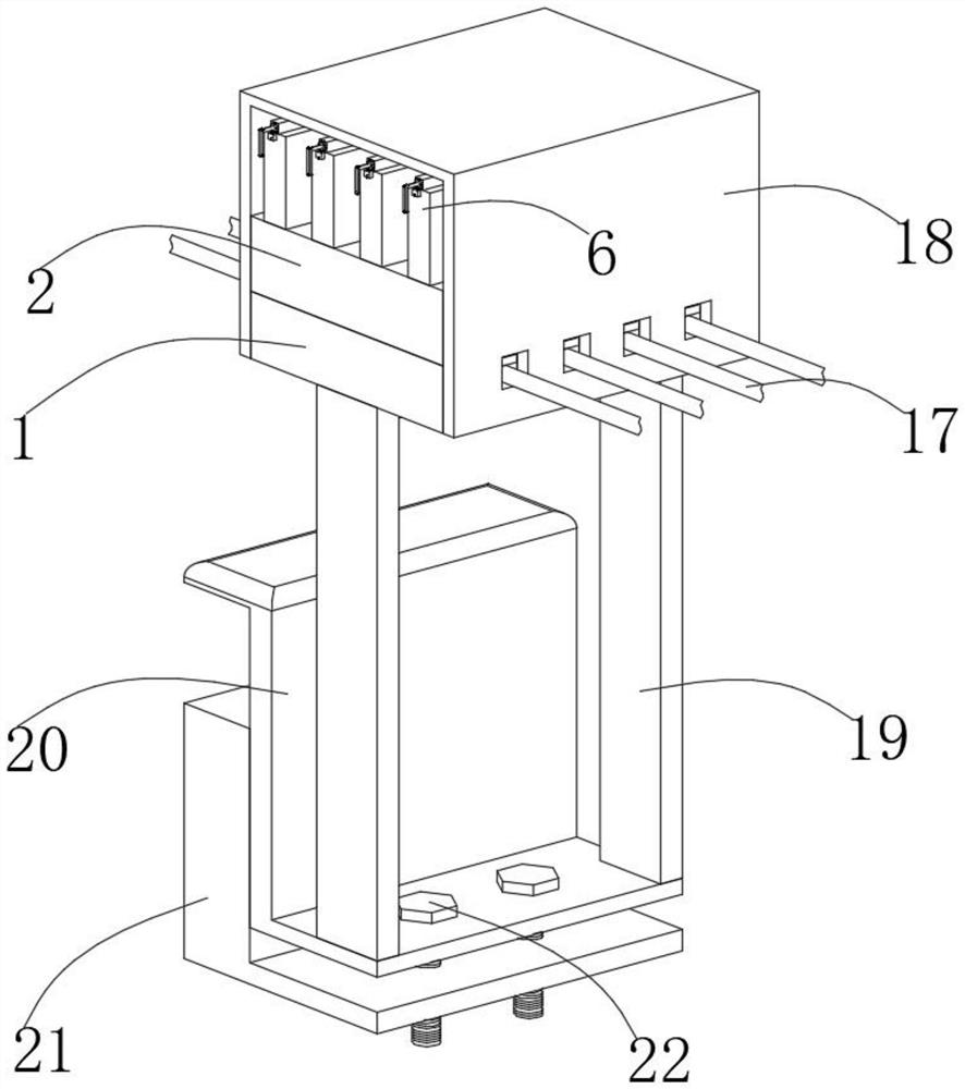
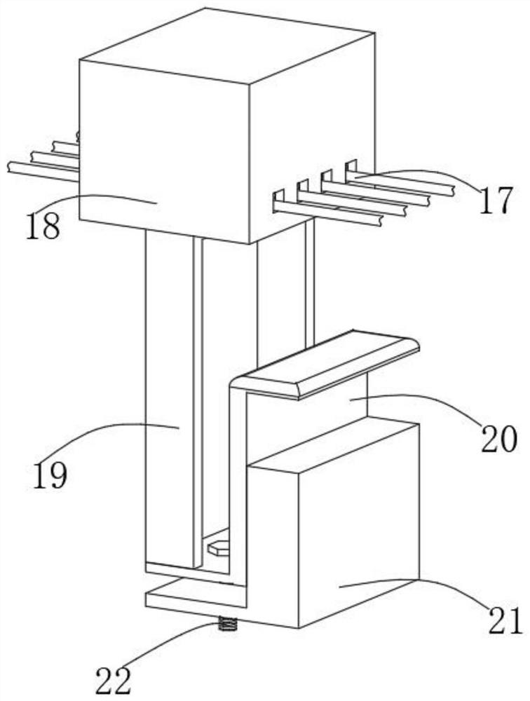
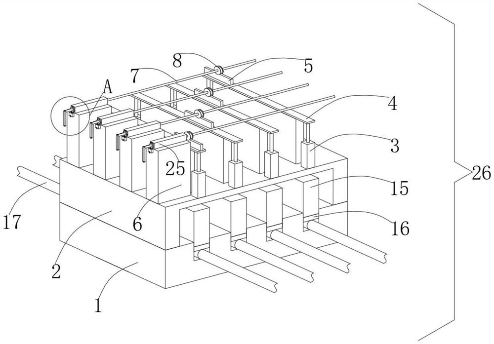
[0028] Embodiment one, with reference to Figure 1-10: A dialysis tube fixing device for nephrology, comprising a control mechanism 26, a protective frame 18 and a fixed block 21, the setting of the control structure 26 enables the equipment to effectively clamp the dialysis tube, and the setting of the protective frame 18 effectively prevents external environment It affects the normal operation of the internal functional parts of the equipment. The establishment of the fixed block 21 cooperates with the positioning plate 20 to effectively fix the equipment on the edge of the hospital bed, so that the equipment can effectively realize its due functions. The control mechanism 26 includes the bottom block 1, the bottom The establishment of the block 1 facilitates the installation and setting of other functional parts of the equipment. The top of the bottom block 1 is equidistantly provided with a plurality of clamping grooves along the horizontal direction. The dialysis tube bod...

Embodiment 2

[0029] Embodiment two, refer to Figure 1-10 : the bottom of the bottom block 1 is fixedly connected with the support plate 19 near the edge of both sides, the setting of the support plate 19 enables the bottom block 1 to be stably connected with the positioning plate 20, and then the equipment can be stably realized with due functions. A positioning plate 20 is fixedly connected between the bottoms of the support plates 19. The setting of the positioning plate 20 enables the equipment to be firmly arranged on the edge of the hospital bed, effectively reducing the effective space occupied by the equipment in the room, and effectively improving the actual use effect of the equipment. The positioning plate 20 Positioning holes are provided on both sides of the top near the edge center of one side. The setting of the positioning holes facilitates the installation of the positioning bolt 22. The top of the fixed block 21 is provided with threaded holes near the center of the side e...

Embodiment 3

[0030] Embodiment three, refer to Figure 1-10 : the inside of each reset frame 3 is located below the corresponding support frame 4 and is provided with a first return spring 14, through the establishment of the first return spring 14, the reset support of the support frame 4 is effectively carried out, so that the equipment can effectively carry out different outer diameter specifications The stable clamping of the dialysis tube body 17, and the fixed connection between the bottom end of each first return spring 14 and the inner bottom surface of the corresponding reset frame 3, the establishment of this structure enables the first return spring 14 to perform its due function stably. The outer surface of each rotating rod 7 is located on the top of the corresponding briquetting block 5 and is equipped with a pressure plate 8. The setting of the pressure plate 8 enables the effective extrusion of the briquetting block 5 by the pressing plate 8 when the rotating rod 7 is turned...


PUM


Abstract

The invention discloses dialysis tube fixing device for the nephrology department. The device comprises a control mechanism, a protection frame and a fixing block, wherein the control mechanism comprises a bottom block, a plurality of clamping grooves are formed in the top of the bottom block in the horizontal direction at equal intervals, a dialysis tube body is arranged in each clamping groove,a supporting frame is fixedly connected to the top of the bottom block, and multiple groups of reset frames are fixedly connected to the edge, close to one side, of the top of the supporting frame atequal intervals in the horizontal direction. According to the dialysis tube fixing device disclosed by the invention, a dialysis tube can be effectively and stably placed through the clamping groovesin the top of the bottom block, a pressing plate effectively extrudes a pressing block by rotating a rotating rod, then the pressing block effectively drives the supporting frame, and the supporting frame drives the clamping block to enable an elastic cushion at the bottom of the clamping block to be matched with the clamping groove to effectively and stably clamp the dialysis tube; and meanwhile,due to the rotation of the rotating rod, an anti-rotation ratchet wheel can only rotate in a single direction under the effective limitation of the control rod, so that the dialysis tube can be stably clamped by the equipment, and due functions of the equipment can be stably realized.

Description

technical field [0001] The invention belongs to the technical field of medical appliances, in particular to a dialysis tube fixing device for nephrology. Background technique [0002] The dialysis concentrate and dialysis water are prepared into qualified dialysate through the dialysate supply system, and pass through the hemodialyzer to perform solute dispersion, osmosis and ultrafiltration with the patient's blood drawn by the blood monitoring alarm system, and the patient's blood after the action passes through the blood The monitoring and alarm system returns to the patient's body, and the liquid after dialysis is discharged from the dialysate supply system as waste liquid, and the whole dialysis process is completed in a continuous cycle. Finally, the dialysis equipment only relies on the suspended connection of the dialysis tube between two points of the patient's patient's site, so that the dialysis tube is easily affected by the external environment, and then the dia...

Claims


Application Information

Patent Timeline
Patent Type & Authority Applications(China)
IPC IPC(8): A61M1/16A61M25/02A61G7/05
CPCA61G7/05A61G2210/20A61M25/02A61M2025/028A61M1/1621
Inventor 叶晓燕
Owner 叶晓燕
Learn More