Driving mode switching method, device and system and automobile

A driving mode and switching device technology, applied in the direction of control devices, etc., can solve problems such as GPF regeneration device damage, impact on vehicle performance, engine damage, etc., to improve system response speed, improve driving experience, and ensure vehicle safety Effect

Inactive Publication Date: 2020-10-16
CHINA FIRST AUTOMOBILE
View PDF7 Cites 6 Cited by
  • Summary
  • Abstract
  • Description
  • Claims
  • Application Information

AI Technical Summary

Problems solved by technology

[0004] The first way to achieve GPF regeneration requires the driver to drive at high speed, but in actual driving, it is often impossible to drive at high speed immediately. For example, in a city, it is difficult to meet the conditions for high-speed driving. The abrupt feeling may easily cause the driver to be unclear, or even make a wrong judgment
The second way is to achieve GPF regeneration. Changing the performance of the engine alone will destroy the driving performance of the whole vehicle, making the working state of the transmitter inconsistent with the originally set driving mode, which will easily cause irreversible damage to the engine over time and reduce the application of the vehicle. service life, and at the same time suddenly changing the working state of the engine alone, it is easy to cause a safety accident
The third way to achieve GPF regeneration requires a long wait to find a suitable working condition. In actual driving, the duration of suitable working conditions is often fragmented, and it is difficult to find a suitable period of time for GPF regeneration. , the long-term waiting makes the GPF regeneration device unable to clean up the vehicle particulate matter in time, which may easily cause damage to the GPF regeneration device, and even affect the performance of the car, resulting in a decline in user experience

Method used


Image

  • Driving mode switching method, device and system and automobile
  • Driving mode switching method, device and system and automobile
  • Driving mode switching method, device and system and automobile

Examples


Embodiment Construction

[0047] In order to make the technical problems solved by the embodiments of the present invention, the technical solutions adopted and the technical effects achieved clearer, the technical solutions of the present invention will be further described below in conjunction with the accompanying drawings and through specific implementation methods. It should be understood that the specific embodiments described here are only used to explain the present invention, but not to limit the present invention. In addition, it should be noted that, for the convenience of description, only parts related to the present invention are shown in the drawings but not all content. Before discussing the exemplary embodiments in more detail, it should be mentioned that some exemplary embodiments are described as processes or methods depicted as flowcharts.

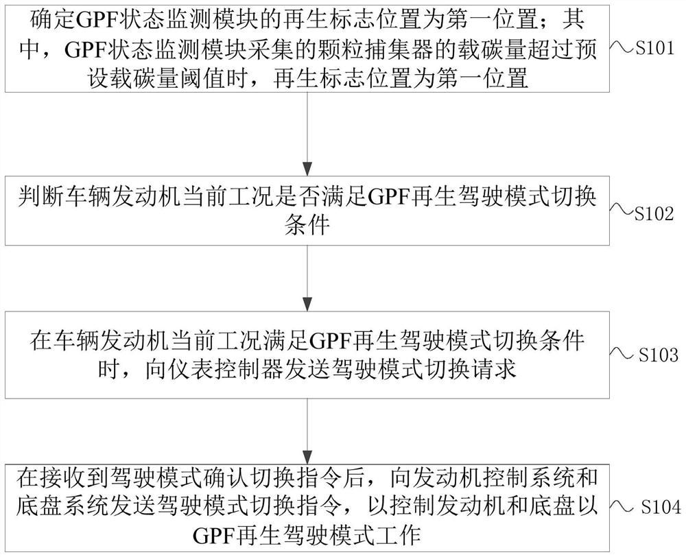
[0048] figure 1 It is a flow chart of a driving mode switching method provided by an embodiment of the present invention, as shown in figure 1 ...


PUM


Abstract

The embodiment of the invention provides a driving mode switching method, device and system and an automobile. The driving mode switching method comprises the steps: determining a regeneration mark position of a GPF state monitoring module as a first position; judging whether the current working condition of a vehicle engine meets a GPF regeneration driving mode switching condition or not; when the current working condition of the vehicle engine meets the GPF regeneration driving mode switching condition, sending a driving mode switching request to an instrument controller; and after a drivingmode switching confirmation instruction is received, sending a driving mode switching instruction to the engine control system and a chassis system so as to control the engine and the chassis to workin the GPF regeneration driving mode. According to the driving mode switching method provided by the embodiment of the invention, the GPF regeneration driving mode can be flexibly and safely switched, the stability in switching the driving mode is improved, and the safety of the whole vehicle, the driving characteristics of the whole vehicle and the subjective willingness of a driver are considered.

Description

technical field [0001] The embodiments of the present invention relate to the technical field of vehicle control, and in particular to a driving mode switching method, device, system and vehicle. Background technique [0002] With the development of society, the country has become more and more strict on the carbon emission control of automobiles, especially after entering the national six exhaust emission standards for gasoline engines, many vehicles are equipped with gasoline engine particulate filters (Gasoline Particulate Filter, referred to as GPF), when the GPF carbon load reaches the preset value, the GPF needs to be regenerated to burn off the trapped particulate oxides. At the same time, when the GPF is regenerated, the engine needs to meet the appropriate working conditions and reach the appropriate temperature. [0003] Among the traditional technologies, the first method recognizes the request for GPF regeneration and prompts the driver on the instrument that "GP...

Claims


Application Information

Patent Timeline
Patent Type & Authority Applications(China)
IPC IPC(8): B60W30/182B60W10/06B60W50/00
CPCB60W10/06B60W30/182B60W50/00B60W2050/0043B60W2710/06
Inventor 张苏铁张建王御任明星谢飞姜洪伟韩亚凝王珊
Owner CHINA FIRST AUTOMOBILE
Why Eureka
Try Eureka