Casting carrying and separating equipment

A technology of castings and equipment, which is applied in the field of casting loading and distributing equipment, can solve problems such as unreasonable casting material distributing, and achieve the effect of saving manual labor

Pending Publication Date: 2020-10-16
林素芹
View PDF7 Cites 21 Cited by
  • Summary
  • Abstract
  • Description
  • Claims
  • Application Information

AI Technical Summary

Problems solved by technology

[0006] The purpose of the present invention is to solve the shortcomings of unreasonable casting material distribution in the prior art, and propose a casting material distribution equipment

Method used


Image

  • Casting carrying and separating equipment
  • Casting carrying and separating equipment
  • Casting carrying and separating equipment

Examples


Embodiment 1

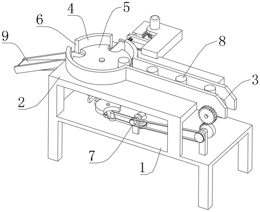
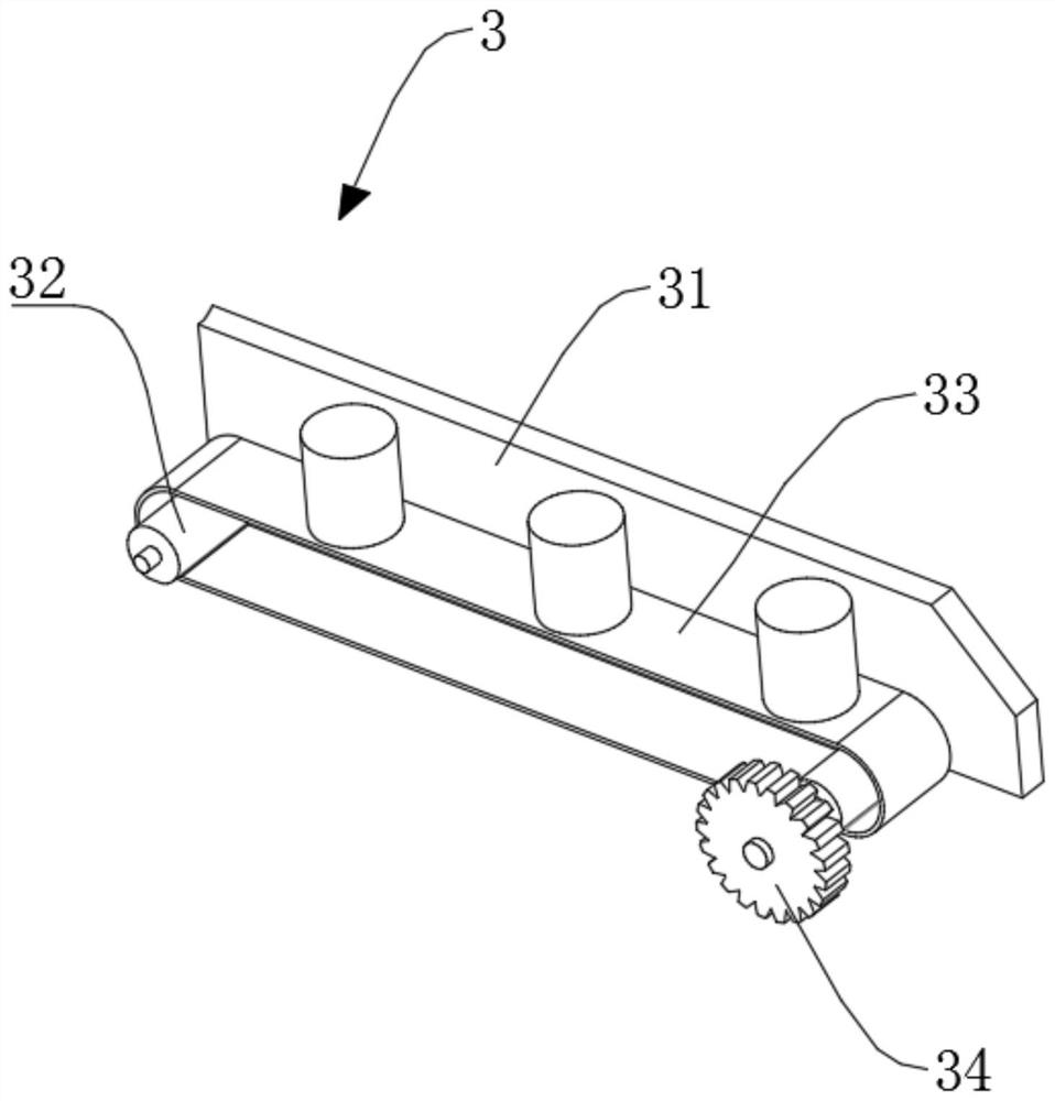
[0028] refer to Figure 1-5 , a casting loading and distributing equipment, comprising a support frame 1, a workbench 2 is fixedly installed on the top of the support frame 1, and a feed mechanism 3 is installed on one end of the workbench 2, and the feed mechanism 3 includes a fixed frame plate 31, two A transmission roller 32, a transmission belt 33 and a transmission gear 34, the fixed frame plate 31 is fixedly installed on the top of the workbench 2, and the two transmission rollers 32 are respectively rotated and installed at the two ends of the fixed frame plate 31 inner side, and the two transmission rollers 32 pass through Conveyor belt 33 transmission connections, wherein the outer end of one conveying roller 32 is coaxially fixedly connected with transmission gear 34, is placed with some corresponding castings 8 on the transmission belt 33, and castings 8 are equidistantly distributed on the transmission belt 33; Through transmission gear 34 The corresponding conveyi...

Embodiment 2

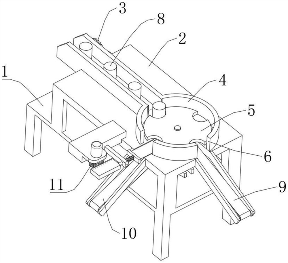
[0035] refer to Figure 1-6 , as another preferred embodiment of the present invention, the difference from Embodiment 1 is that the bottom end of one of the discharge ports 6 is equipped with a second material distribution mechanism 11, and the second material distribution mechanism 11 includes a fixed seat 111, and the fixed seat 111 is fixedly installed on the top of the workbench 2, and one side of the fixed seat 111 is fixedly equipped with a guide seat 112, and one end of the guide seat 112 is slidably installed with a through slide bar 115, and one end of the slide bar 115 is fixedly installed with a limit plate 114, limiting The side of the position plate 114 away from the slide bar 115 is fixedly equipped with a slide plate 113, the slide plate 113 is located on the inner side of the mounting seat 4, and is slidably connected with the bottom surface of the mounting seat 4, and a return is installed between the limit plate 114 and the guide seat 112. The spring 116 and...


PUM


Abstract

The invention relates to the technical field of casting separation, in particular to casting carrying and separating equipment. The casting carrying and separating equipment comprises a supporting frame. A workbench is installed at the top of the supporting frame. A feeding mechanism is installed at one end of the workbench and comprises a fixed frame plate, two conveying rollers, a conveying beltand a transmission gear. An installation seat is installed at the output end of the conveying belt and is fixedly connected with the top of the workbench. A material separating mechanism is installedon the inner side of the installation seat and comprises a material separating disc. A rotary shaft is fixedly installed at the bottom of the material separating disc. A rotary seat is fixedly installed at the bottom end of the rotary shaft. A plurality of butt joint grooves are formed in the outer extending part of the rotary seat. A rotary disc is arranged on the outer extending part of the rotary seat. The bottom of the rotary disc is fixedly provided with a fixed plate. One end of the top of the fixed plate is fixedly provided with a lug. By means of the equipment, perfect cooperation ofautomatic feeding, automatic separating and automatic discharging of castings is achieved, the manual labor amount is greatly saved, the castings can be arranged and discharged in order, and accumulation is avoided.

Description

technical field [0001] The invention relates to the technical field of casting materials distribution, in particular to a casting loading and distribution equipment. Background technique [0002] The application of castings has a long history. In ancient times, people used castings to make and some living utensils; in modern times, castings are mainly used as blanks for machine parts, and some precision castings can also be directly used as parts of machines. Castings occupy a large part of mechanical products. For example, in tractors, the weight of castings accounts for about 50-70% of the weight of the whole machine, 40-70% in agricultural machinery, and 70-90% in machine tools and internal combustion engines. Among all kinds of castings, castings for machinery have the most varieties, the most complex shapes, and the largest consumption, accounting for about 60% of the total output of castings, followed by ingot molds for metallurgy, pipes for engineering, and some tools...

Claims


Application Information

Patent Timeline
Patent Type & Authority Applications(China)
IPC IPC(8): B65G47/24B65G47/64B65G47/72B65G47/84
CPCB65G47/648B65G47/72B65G47/846B65G47/24
Inventor 林素芹
Owner 林素芹
Why Eureka
Try Eureka