
Kiln thermal insulating wall and mounting method

An installation method and insulation wall technology, applied in the field of kilns, can solve the problems of large heat dissipation area of ​​the installation plate of the insulation layer, increased energy consumption of kiln operation, unfavorable kiln heat preservation and energy saving, etc., and achieve the reduction of kiln heat loss and energy saving Reduced power consumption and easy installation

Active Publication Date: 2020-10-16
西安力元炉窑自动化设备有限公司
View PDF10 Cites 0 Cited by
  • Summary
  • Abstract
  • Description
  • Claims
  • Application Information

AI Technical Summary

Problems solved by technology

[0004] The invention provides a kiln insulation wall and an installation method to overcome the problems in the prior art that the heat dissipation area of ​​the installation plate of the insulation layer is large, the heat loss is serious, the energy consumption of the kiln operation is increased, and it is not conducive to the kiln insulation and energy saving

Method used


Image

  • Kiln thermal insulating wall and mounting method
  • Kiln thermal insulating wall and mounting method
  • Kiln thermal insulating wall and mounting method

Examples


Embodiment Construction

[0039] In order to make the purpose, technical solutions and advantages of the embodiments of the present invention clearer, the technical solutions in the embodiments of the present invention will be clearly and completely described below in conjunction with the drawings in the embodiments of the present invention. Obviously, the described embodiments It is a part of embodiments of the present invention, but not all embodiments. Based on the embodiments of the present invention, all other embodiments obtained by persons of ordinary skill in the art without creative efforts fall within the protection scope of the present invention.

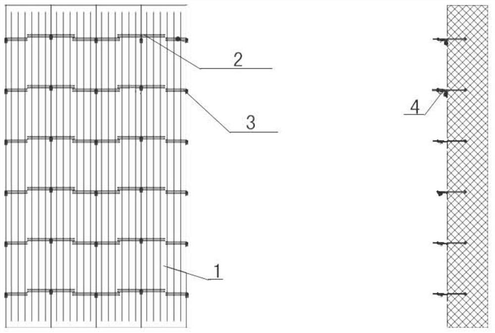
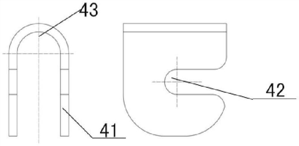
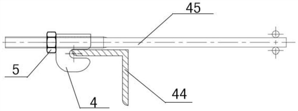
[0040] figure 1 It is a structural schematic diagram of Embodiment 1 of a furnace insulation wall of the present invention; figure 2 It is a structural schematic diagram of a cotton brazing hook in a furnace insulation wall of the present invention; image 3 It is a schematic diagram of installation of a cotton brazing hook in a furnace insulat...


PUM


Abstract

The invention provides a kiln thermal insulating wall. The kiln thermal insulating wall comprises cotton bales, T-shaped cotton bars, L-shaped cotton bars and cotton bar hooks. The cotton bales are fixed to a side beam and a top beam of a kiln through the T-shaped cotton bars or the L-shaped cotton bars. Cross rod of the T-shaped cotton bars or the L-shaped cotton bars are inserted into the cottonbales, and vertical rods of the T-shaped cotton bars or the L-shaped cotton bars are connected with the side beam or the top beam through the cotton bar hooks. Each cotton bar hook comprises a U-shaped connecting sheet, the side face of each U-shaped connecting sheet comprises a groove, and the vertical rods of the T-shaped cotton bars or the L-shaped cotton bars penetrate through the bends of the U-shaped connecting sheets and are fixed through fixing parts. The grooves of the U-shaped connecting sheets and the side beam or the top beam are fastened. The kiln thermal insulating wall is easyto mount and small in heat radiating area, the kiln heat loss is greatly reduced, and energy consumption is reduced; and kiln heat insulating and energy saving are benefited, and the equipment use enterprise cost is reduced.

Description

technical field [0001] The invention relates to kiln technology, in particular to a kiln insulation wall and an installation method. Background technique [0002] At present, most kiln manufacturers choose standard fiber modules as the refractory and thermal insulation materials for kilns. For large equipment such as mobile tunnel kilns, the size of standard fiber modules is 300*300*200. Before installation, it is necessary to draw a line to determine the specific installation of the module. location, the installation process is complicated, the installation period is long, the installation location is fixed, and cannot be adjusted flexibly; [0003] The installation method of the standard fiber module is that the screw passes through the L-shaped anchor with holes and connects with the nut welded on the installation plate. The installation plate has a large heat dissipation area and serious heat loss, which increases the energy consumption of the kiln, which is not conduciv...

Claims


Application Information

Patent Timeline
IPC IPC(8): F27D1/00F27D1/02F27D1/14
CPCF27D1/0033F27D1/02F27D1/14
Inventor 柏飞柏昊仓
Owner 西安力元炉窑自动化设备有限公司
Learn More