
Improved drawer adjusting structure

A technology for adjusting structures and drawers, which can be applied to drawers, furniture parts, household appliances, etc., and can solve problems such as opening blockage, failure to meet production and users, and inability to adjust drawers.

Pending Publication Date: 2020-10-20
GUANGDONG DTC HARDWARE PRECISION MFG CO LTD
View PDF1 Cites 0 Cited by
  • Summary
  • Abstract
  • Description
  • Claims
  • Application Information

AI Technical Summary

Problems solved by technology

It is said that the front of the drawer is provided with a fulcrum, which acts on the moving slide rail, the bottom plate is assembled on the slot of the side plate, and is supported on the convex part of the moving slide rail, and the reference plane is the moving direction of the slide rail assembly. , the positive and negative angles of the drawer relative to the reference plane are adjusted through the movable parts; however, in order to facilitate the adjustment of the adjustment part, an opening is provided on one side of the side plate, and the user can adjust the adjustment part through the opening through tools or manually , this not only affects the integrity of the appearance of the side panels, but the user will easily touch the opening when putting in and taking out the items, which will cause the user to scratch, and the stored items will also easily enter the opening, causing the opening to be blocked, making the drawer Unable to adjust, unable to meet the needs of production and users

Method used


Image

  • Improved drawer adjusting structure
  • Improved drawer adjusting structure
  • Improved drawer adjusting structure

Examples


Embodiment Construction

[0029] The present invention will be further described below in conjunction with the accompanying drawings and embodiments.

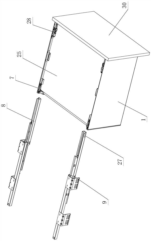
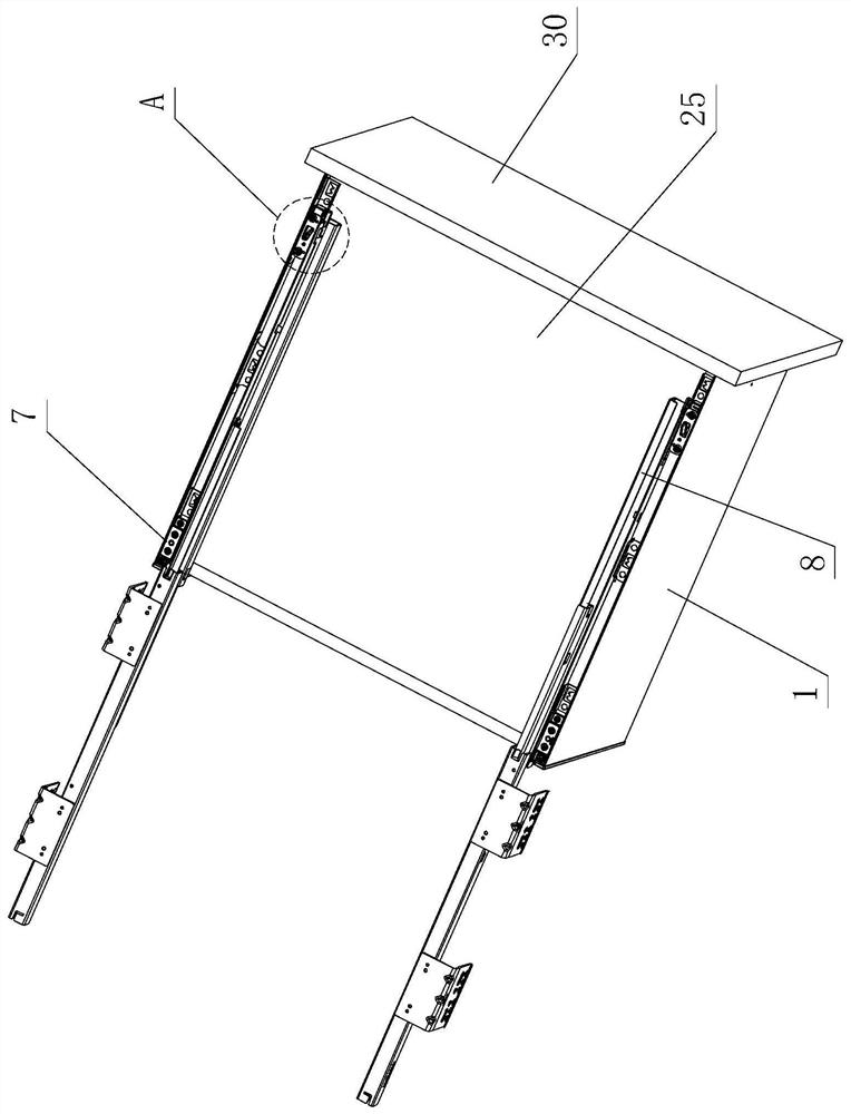
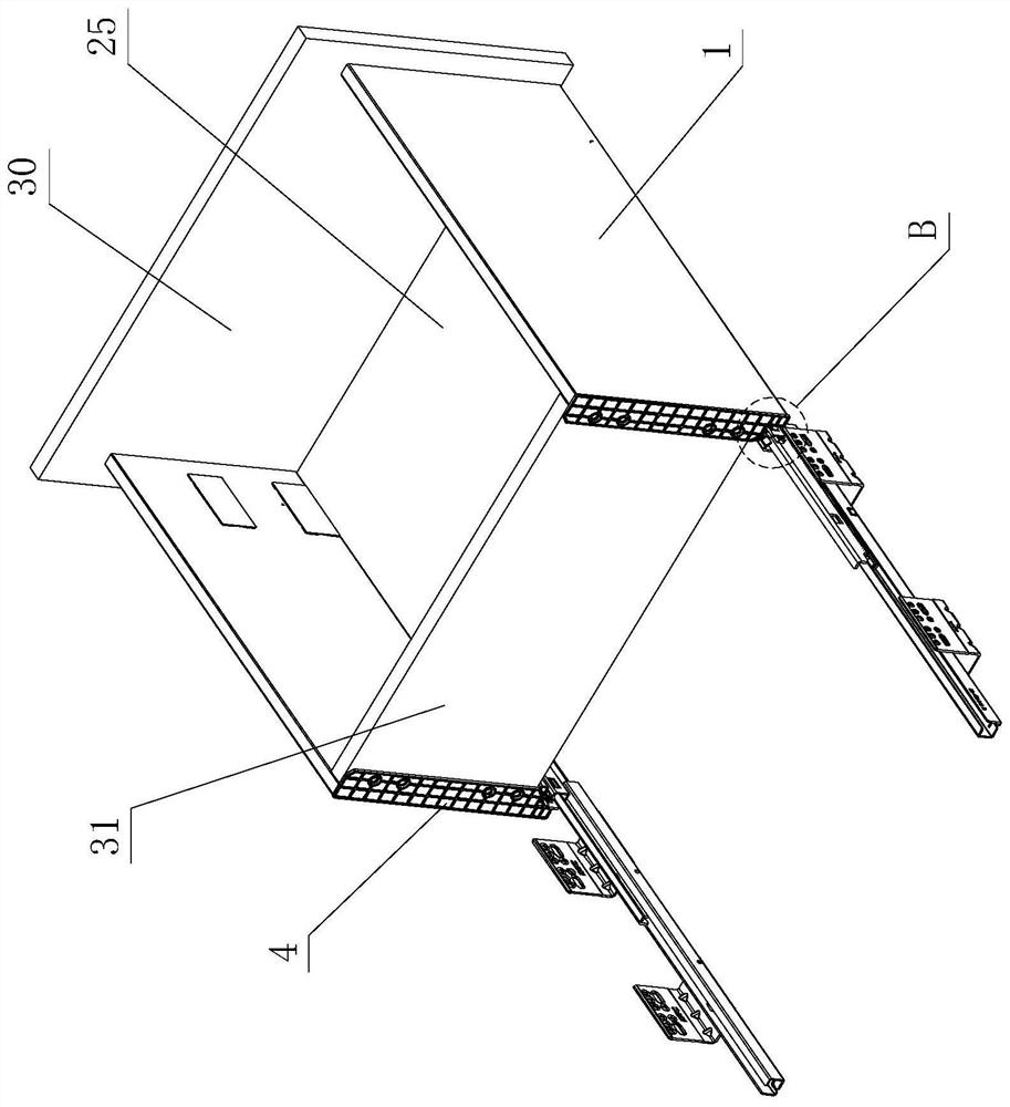
[0030] see Figure 1-Figure 14 , the improved drawer adjustment structure includes a side plate 1, the side plate 1 is provided with a cavity 2 inside, and the lower part is integrally formed or separately provided with a connecting part 3; wherein, the rear end of the cavity 2 is provided with a rear connector 4, and the rear The connecting part 4 is made of plastic, and a movable part 5 is arranged on it, and the movable part 5 is made of plastic, and an adapter part 6 made of metal material is arranged on it, and an adjustment assembly 7 is arranged under the connecting part 3 , the adjustment assembly 7 is driven and connected with the adapter 6; the adjustment assembly 7 is adjusted by a tool or manually, and at least drives the rear connecting member 4 to move up and down relative to the movable member 5 and the adapter 6.

[0031] The movable pa...


PUM


Abstract

The invention provides an improved drawer adjusting structure which comprises a side plate, a cavity is formed in the side plate, and the lower portion of the side plate is integrally formed or provided with a connecting part in a split mode, wherein a rear connecting piece is arranged at the rear end of the cavity, the rear connecting piece is made of plastic, a movable piece is arranged on the rear connecting piece, the movable piece is made of plastic, an adapter piece made of a metal material is arranged on the movable piece, an adjusting assembly is arranged below the connecting part, andthe adjusting assembly is in driving connection with the adapter piece; the adjusting assembly is acted through a tool or manually, and the rear connecting piece is at least driven to move up and down relative to the movable piece and the adapter piece. According to the invention, the structure is improved; the driving stability between the adapter piece and the adjusting assembly can be improved, meanwhile, as the adjusting assembly is arranged below the connecting part in a hidden mode, the touch of a user can be avoided, the drawer is safer and more reliable in use and more exquisite and simpler in appearance, and the adjustment and positioning between the rear connecting piece and the movable piece and between the rear connecting piece and the adapter piece can be more stable, accurate and firm.

Description

technical field [0001] The invention relates to an improved drawer adjustment structure. Background technique [0002] Chinese Patent Document No. CN103844674A disclosed a position adjustment mechanism for drawers on June 11, 2014. It includes side plates, bottom plates and slide rail assemblies for opening and closing drawers. The front connecting piece and the rear connecting piece connecting the rear backplane are provided with slots on the side plates, and the bottom plate is assembled on the slots. The rear connecting piece includes a fixed part and a movable part, and an extension part is arranged on the movable part and supports On the moving slide rail of the slide rail assembly, the rear end of the moving slide rail is provided with a locating piece, and is connected with the extension part at least during assembly; the front of the drawer is provided with a fulcrum, and acts on the moving slide rail, The movable part of the rear connecting piece realizes the adjus...

Claims


Application Information

Patent Timeline
Patent Type & Authority Applications(China)
IPC IPC(8): A47B88/407A47B88/90
CPCA47B88/407A47B88/90
Inventor 伍志勇
Owner GUANGDONG DTC HARDWARE PRECISION MFG CO LTD
Learn More