
Plastic package residual glue removing device suitable for frame type semiconductor

A technology for removing glue residue and semiconductor, applied in the field of plastic packaging of semiconductor products, which can solve the problems of affecting tool life, electrical risk, tool damage, etc.

Pending Publication Date: 2020-10-20
YANGZHOU YANGJIE ELECTRONIC TECH CO LTD
View PDF0 Cites 0 Cited by
  • Summary
  • Abstract
  • Description
  • Claims
  • Application Information

AI Technical Summary

Problems solved by technology

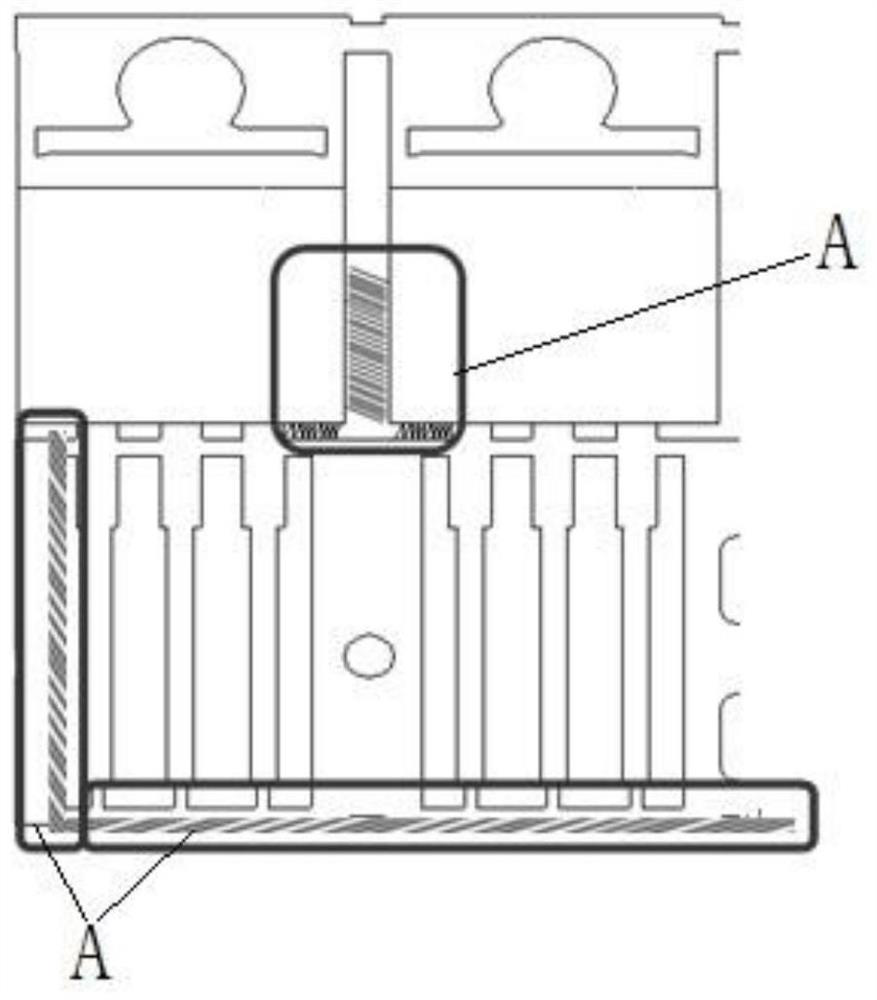
[0002] In the plastic sealing process of frame-type semiconductor products, due to some uncontrollable factors, there are plastic sealant residues. In extreme cases, the overflowed residual plastic sealant will cause a conjoined situation. If these residual plastics are not cleaned before electroplating, they will affect the appearance of the product. Moreover, cutting ribs will cause damage to the tool and affect the life of the tool, and tool wear will pose a risk to electrical properties; therefore, manual removal is required, and manual removal adds an uncontrollable process, reducing production efficiency, and manual removal Can't guarantee complete removal
For example, the traditional manual use of knives to remove residual glue, there are cases where the body of the material and the residual glue on the side of the frame cannot be removed

Method used


Image

  • Plastic package residual glue removing device suitable for frame type semiconductor
  • Plastic package residual glue removing device suitable for frame type semiconductor

Examples


Embodiment Construction

[0034] Hereinafter, the present invention will be specifically introduced with reference to the drawings and specific embodiments.

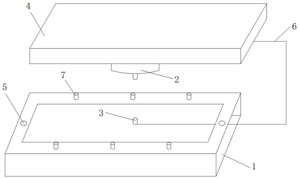
[0035] A plastic encapsulation residue removal device suitable for frame type semiconductors is composed of a control device, a frame, a laser generator, a laser receiver, a residue detection device and a plane positioning device.

[0036] Several limit blocks for fixing semiconductors and infrared sensors for sensing semiconductors are arranged on the frame. The laser generator is suspended on the top of the frame through a plane positioning device, and the plane positioning device includes a horizontal X axis and a longitudinal Y axis respectively driven by a control device through a motor.

[0037] The laser receiver is arranged at the bottom of the frame corresponding to the laser generator, and the laser receiver and the laser generator are fixed by a connecting rod, and the plane displacement can be synchronized to ensure emission and reception.

...


PUM


Abstract

The invention discloses a plastic package residual glue removing device suitable for a frame type semiconductor. The plastic package residual glue removing device comprises a frame used for placing asemiconductor, a laser generator is suspended at the top of the frame, a laser receiver is arranged at the bottom of the frame and corresponds to the laser generator, a semiconductor induction deviceis arranged on the frame, a control device drives the laser generator to be started and stopped according to feedback of the induction device, and the control device adjusts the power of the laser generator according to the light intensity fed back by the laser receiver. According to the plastic package residual glue removing device, the frame serves as a base frame and provides base coordinates,residual glue and the position of the residual glue are identified through an image-text comparison module, the laser generator is moved through a plane positioning device, the removal state of the residual glue is judged through the fact that the light intensity of laser received by the laser receiver is higher than that of local laser, and the residual glue with different thicknesses is removedin a targeted mode through the laser generator with gradually-changing power, and the effects of energy conservation and efficiency improvement are achieved; and the glue removing device can effectively remove the connected residual glue, is good in removal effect and high in efficiency, effectively improves the appearance quality of a product, and has very high practicability and wide applicability.

Description

Technical field [0001] The present invention designs a residual glue removing device, in particular to a plastic encapsulation residual glue removing device suitable for frame type semiconductors, and belongs to the technical field of semiconductor product plastic encapsulation. Background technique [0002] In the molding process of frame-type semiconductor products, due to some uncontrollable factors, there will be plastic molding residues. In extreme cases, the overflow of the residual molding glue will cause a conjoined condition. These residues will not be cleanly removed before electroplating, which will affect the appearance of the product. In addition, cutting ribs will cause tool damage and affect tool life, and tool wear will cause electrical risks; therefore, manual removal is required, and manual removal operation adds an uncontrollable process, reducing production efficiency, and manual removal It cannot be guaranteed to be completely removed. For example, the tradi...

Claims


Application Information

Patent Timeline
IPC IPC(8): B08B7/00H01L21/67B05C11/10
CPCB05C11/1039B08B7/0042H01L21/67011
Inventor 林剑河景昌忠王毅
Owner YANGZHOU YANGJIE ELECTRONIC TECH CO LTD
Learn More