Three-point positioning type combined circular cutter seat of gull-wing ejector block structure

A three-point positioning, circular blade technology, applied in the direction of cutting tools, shearing equipment, shearing devices, etc. for shearing machines, can solve the problems of unsupported longitudinal shearing tools and damage to longitudinal shearing tools.

Pending Publication Date: 2020-10-20
马鞍山市金菲硬质合金刀具有限公司
View PDF0 Cites 1 Cited by
  • Summary
  • Abstract
  • Description
  • Claims
  • Application Information

AI Technical Summary

Problems solved by technology

[0002] Slitting machine, also known as slitting line, slitting machine or slitting machine, is used to uncoil, slitting, and rewind metal coils into strips of required width. It is suitable for processing cold-rolled and hot-rolled carbon steel, Silicon steel, tinplate, stainless steel and various metal materials after surface coating, slitting machine equipment has the advantages of convenient operation, high cutting quality and high material utilization rate, and has the characteristics of stepless speed regulation of cutting speed, widely used in transformers In industries such as electrical machinery, home appliances, automobiles, building materials and packaging, the longitudinal cutting work of various plates, aluminum strips and tinplate, among which the blade of the slitting machine is also called the disc blade, which is used in the slitting equipment of the metal sheet industry. This kind of slitting tool is named for its longitudinal occlusal slitting of the upper and lower sets of knives. It is generally made of high-speed steel or hard alloy. It has undergone a complete set of vacuum heat treatment and cryogenic treatment to ensure uniform hardness. High longitudinal cutting performance, the three-point positioning cutting tool of the prior art slitting machine is mainly installed on the rotating shaft of the equipment, and the cutting is driven by the rotating shaft, and the cutting height is fixed and cannot be changed, and the bottom of the slitting tool has no support , during the slitting process, the slitting tool may be damaged due to the heavy material sheet

Method used


Image

  • Three-point positioning type combined circular cutter seat of gull-wing ejector block structure
  • Three-point positioning type combined circular cutter seat of gull-wing ejector block structure
  • Three-point positioning type combined circular cutter seat of gull-wing ejector block structure

Examples


Embodiment 1

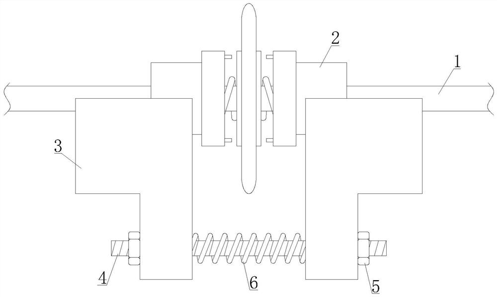
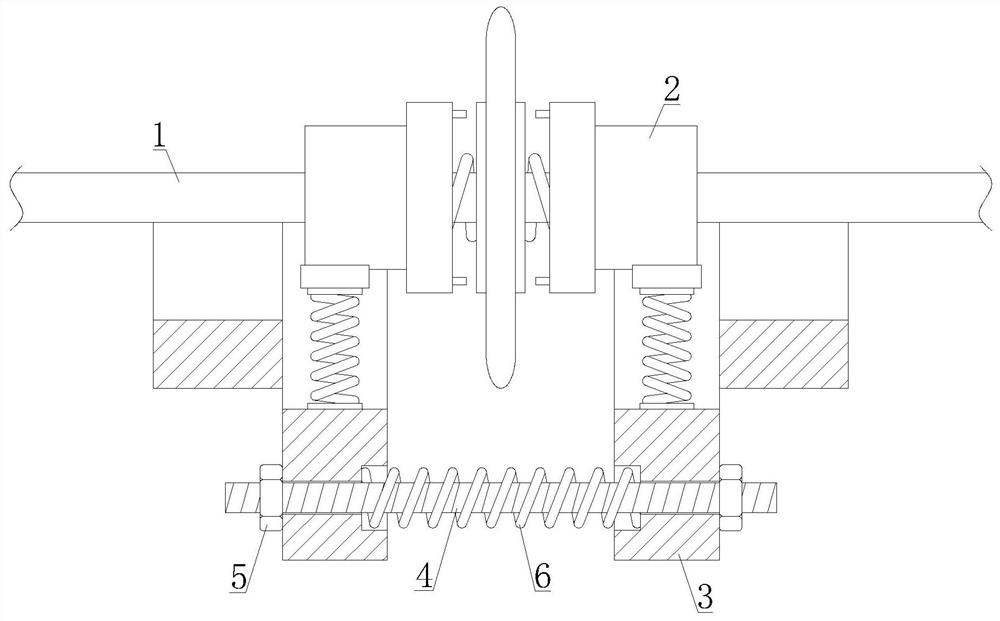
[0026] see Figure 1-Figure 2 , a three-point positioning combined circular blade tool seat of a gull-wing top block structure, including a slitting main shaft 1, a three-point slitting tool 2, a gull-wing support unit 3, an adjusting screw 4, an adjusting nut 5 and an adjusting Spring 6, a three-point slitting tool 2 is installed on the slitting main shaft 1, the left and right ends of the lower side of the three-point slitting tool 2 are respectively provided with a gull-wing support unit 3, and an adjusting screw is installed between the lower sides of the gull-wing support unit 3 4. Adjusting nuts 5 are respectively installed at both ends of the adjusting screw 4, and an adjusting spring 6 is provided on the outside of the adjusting screw 4 between the gull-wing support units 3. The adjustment spring 6 is assembled to form a gull-wing type support top block.

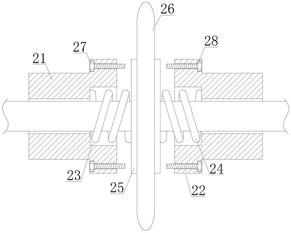
[0027] see image 3 , the three-point slitting tool 2 includes an outer clamping sleeve 21, an inner clamping sl...

Embodiment 2

[0032] see Figure 1-Figure 2 , a three-point positioning combined circular blade tool seat of a gull-wing top block structure, including a slitting main shaft 1, a three-point slitting tool 2, a gull-wing support unit 3, an adjusting screw 4, an adjusting nut 5 and an adjusting Spring 6, a three-point slitting tool 2 is installed on the slitting main shaft 1, the left and right ends of the lower side of the three-point slitting tool 2 are respectively provided with a gull-wing support unit 3, and an adjusting screw is installed between the lower sides of the gull-wing support unit 3 4. Adjusting nuts 5 are respectively installed at both ends of the adjusting screw 4, and an adjusting spring 6 is provided on the outside of the adjusting screw 4 between the gull-wing support units 3. The adjustment spring 6 is assembled to form a gull-wing type support top block.

[0033] see image 3 , the three-point slitting tool 2 includes an outer clamping sleeve 21, an inner clamping sl...


PUM


Abstract

The invention discloses a three-point positioning type combined circular cutter seat of a gull-wing ejector block structure. The three-point positioning type combined circular cutter seat comprises alongitudinal shearing main shaft, a three-point longitudinal shearing tool, a gull-wing supporting unit, an adjusting screw rod, adjusting nuts and an adjusting spring, wherein the gull-wing supporting unit has two modes; in the first mode, an upper ejector block and a lower ejector block are internally provided with external movable clamping openings and inner movable clamping openings to bear the longitudinal shearing main shaft and the three-point longitudinal shearing tool, moreover, and the inner movable clamping openings are internally provided with buffering pieces and buffering springsto bear the three-point longitudinal shearing tool; in the second mode, movable supporting pieces and movable clamping seats are in a separated mode, the movable supporting pieces can be rotated by any angle through inner moving shafts, the longitudinal shearing main shaft and the three-point longitudinal shearing tool are borne by segmented slide grooves in the movable supporting pieces, accordingly, the supporting height of supporting ejector blocks can be flexibly adjusted, the supporting problem of the longitudinal shearing main shaft and the three-point longitudinal shearing tool is solved, and the situation that the longitudinal shearing tool is damaged due to the fact that a material plate is too heavy is effectively prevented.

Description

technical field [0001] The invention relates to the technical field of three-point slitting blades, in particular to a three-point positioning combined circular blade seat of a gull-wing top block structure. Background technique [0002] Slitting machine, also known as slitting line, slitting machine or slitting machine, is used to uncoil, slitting, and rewind metal coils into strips of required width. It is suitable for processing cold-rolled and hot-rolled carbon steel, Silicon steel, tinplate, stainless steel and various metal materials after surface coating, slitting machine equipment has the advantages of convenient operation, high cutting quality and high material utilization rate, and has the characteristics of stepless speed regulation of cutting speed, widely used in transformers In industries such as electrical machinery, home appliances, automobiles, building materials and packaging, the longitudinal cutting work of various plates, aluminum strips and tinplate, am...

Claims


Application Information

Patent Timeline
IPC IPC(8): B23D19/00B23D35/00
CPCB23D19/00B23D35/004
Inventor 陈学金陈鑫旸袁炳海
Owner 马鞍山市金菲硬质合金刀具有限公司
Why Eureka
Try Eureka