Rapid emptying ballast tank

A technology of ballast tanks and ballast water tanks, which is applied to some cabins in the hull, ships, hulls, etc., and can solve problems such as large spacing, reduced drainage efficiency, and easy blockage of water holes

Pending Publication Date: 2020-10-20
SHANGHAI MERCHANT SHIP DESIGN & RES INST
View PDF0 Cites 0 Cited by
  • Summary
  • Abstract
  • Description
  • Claims
  • Application Information

AI Technical Summary

Problems solved by technology

The diameter of the water holes is small and the distance between them is large, so the effect on the drainage efficiency is not ideal;
[0006] 2) The water hole is easy to block
Sediment impurities and pollutants contained in seawater can easily cause blockage of flow holes; improper welding may also block flow holes, further reducing drainage efficiency;

Method used


Image

  • Rapid emptying ballast tank
  • Rapid emptying ballast tank
  • Rapid emptying ballast tank

Examples


Embodiment Construction

[0027] The present invention will be further described below in conjunction with the accompanying drawings and specific embodiments.

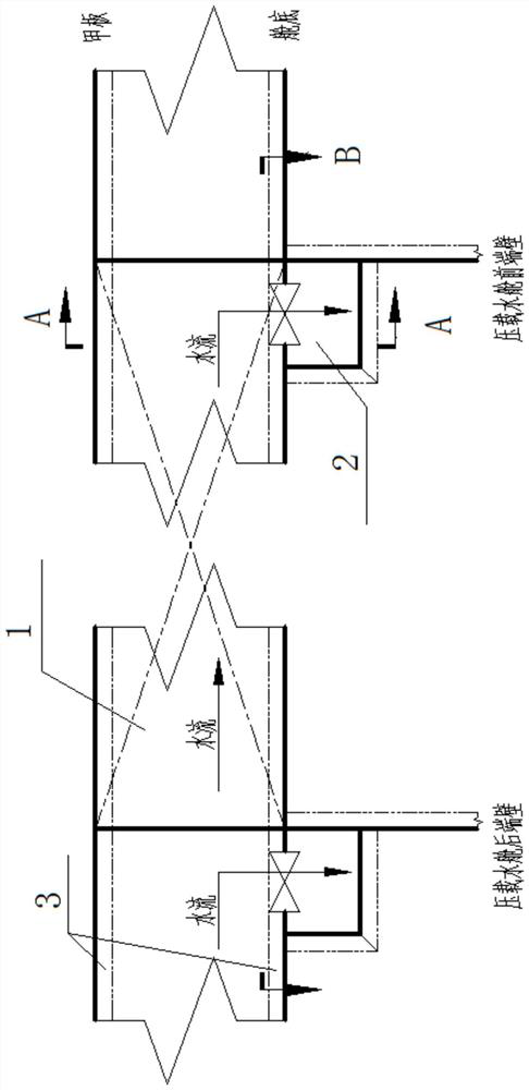
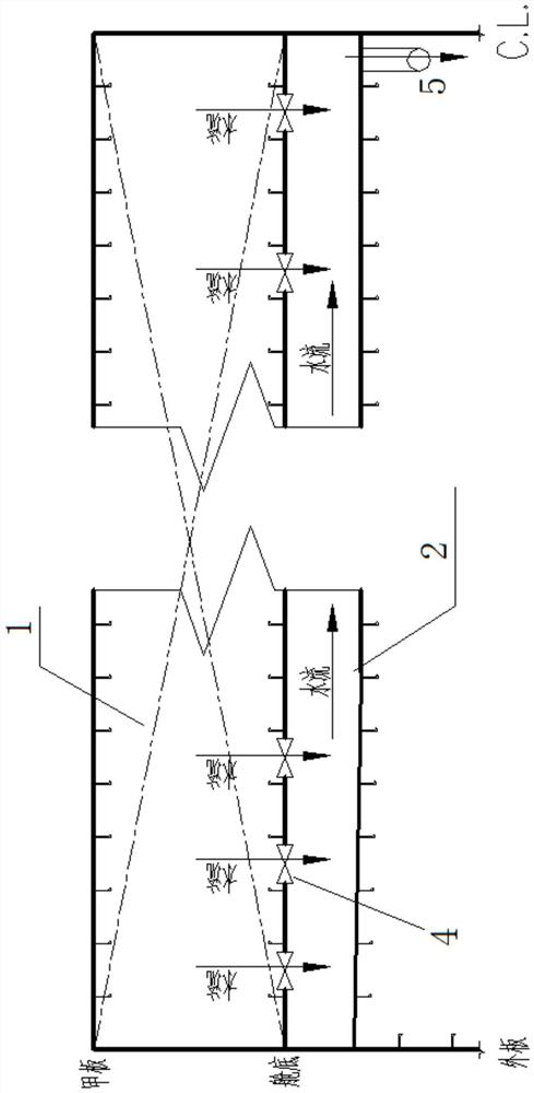
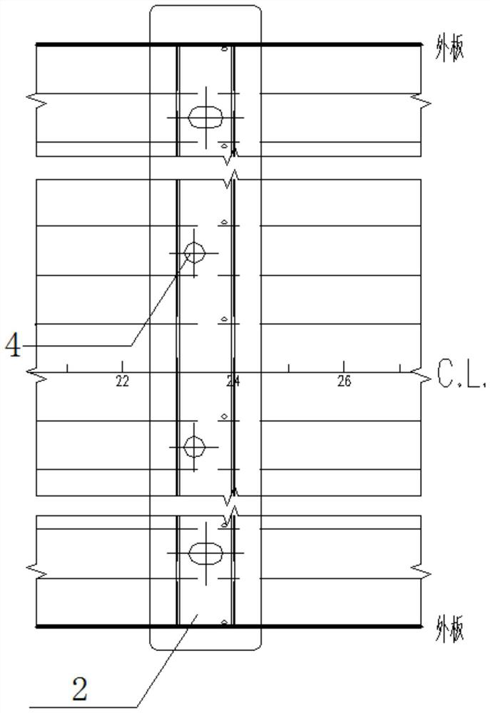
[0028] see Figure 1-Figure 3 , a fast emptying ballast tank, comprising a ballast water tank 1, at the bottom of the ballast water tank 1, a diversion groove 2 is arranged outside the ballast water tank 1, and the direction of the diversion groove 2 is perpendicular to The direction of the upwardly protruding aggregate 4 at the bottom of the ballast water tank; select the positions between several adjacent aggregates 4 to set diversion holes 4, so that the ballast water tank 1 and the diversion groove 2 are kept in communication; At least one ballast tank water outlet 5 is provided at the bottom of the diversion tank 2 .

[0029] In this example, see Figure 1-3 , the transverse section and longitudinal section of the ballast water tank 1 are both rectangular, the aggregates 4 are arranged along the axial direction of the hull, the diversion...


PUM


Abstract

The invention relates to a rapid emptying ballast tank, and belongs to the technical field of ship ballast tank design. The rapid emptying ballast tank comprises a water ballast tank, wherein a flow guide groove is formed in the bottom of the water ballast tank and located outside the water ballast tank, and the direction of the flow guide groove is perpendicular to the direction of an upwards-protruding aggregate at the bottom of the water ballast tank; flow guide holes are formed in positions between a plurality of adjacent aggregates so as to enable the ballast water tank to be communicatedwith the flow guide groove; at least one ballast water tank water flow outlet is formed in the bottom of the flow guide groove. When drainage operation is carried out, ballast water is not directly discharged from the ballast water tank any more, but flows into the flow guide groove through the flow guide holes and then is discharged. The diameter of the flow guide hole is far larger than that ofan originally-designed water flowing hole, blocking is not likely to happen, and the drainage flow speed is greatly increased; the flow guide groove aggregate does not occupy the space in the flow guide groove, the problem that the aggregate in the cabin occupies the volume of flowing water is solved, the circulation area is increased, the drainage flow speed is increased, and thus the drainage efficiency is improved.

Description

technical field [0001] The invention relates to a fast emptying ballast tank, belonging to the technical field of ship ballast tank design. Background technique [0002] Some types of ships realize the floating and diving of the ship by loading and emptying the ballast water, changing the floating state of the ship, and completing engineering operations. Therefore, reducing the loading and emptying time of ballast water will reduce the working time and improve the working efficiency. [0003] The aggregates and girders in the ballast water tank are generally large in size, occupying a large internal volume, reducing the circulation area during drainage, reducing the emptying efficiency, and directly increasing the working time. In order to improve the emptying efficiency of ballast water, most designs currently adopt the method of building inclined ballast water tanks, and at the same time, holes are made on the frames and girder webs in the ballast water tanks. The inclin...

Claims


Application Information

Patent Timeline
Patent Type & Authority Applications(China)
IPC IPC(8): B63B11/04
CPCB63B11/04
Inventor 李思琦王永成
Owner SHANGHAI MERCHANT SHIP DESIGN & RES INST
Why Eureka
Try Eureka