
In-furnace transfer device with good black patch-preventing effect for round steel heating furnace

A transmission device and heating furnace technology, applied in the field of heating furnace, can solve the problem of uneven heating of billets, and achieve the effects of preventing uneven heating, easy maintenance and adjustment, and novel structure

Active Publication Date: 2020-10-20
YIYANG SHENGLI CHEM IND
View PDF6 Cites 3 Cited by
  • Summary
  • Abstract
  • Description
  • Claims
  • Application Information

AI Technical Summary

Problems solved by technology

[0004] Based on the technical problem that the lower surface of the beam support bar is always in contact with the lower surface of the billet when the existing heating device is feeding in the furnace, which easily leads to uneven heating of the billet, the present invention proposes a round steel heating furnace. Furnace conveying device with good printing effect

Method used


Image

  • In-furnace transfer device with good black patch-preventing effect for round steel heating furnace
  • In-furnace transfer device with good black patch-preventing effect for round steel heating furnace
  • In-furnace transfer device with good black patch-preventing effect for round steel heating furnace

Examples


Embodiment 1

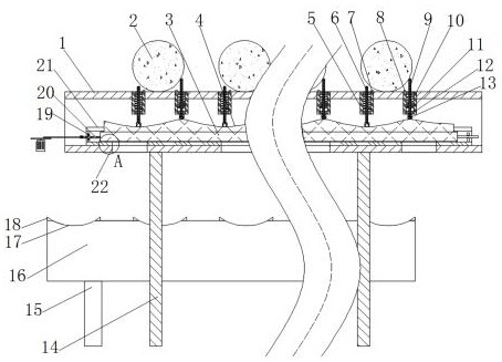
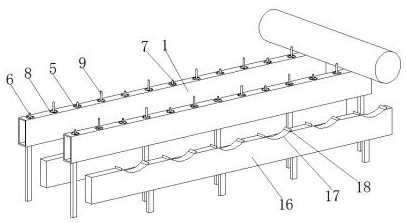
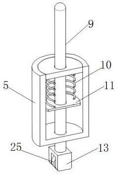
[0029] refer to Figure 1-5 , an in-furnace conveying device with good anti-black mark effect for a round steel heating furnace, comprising a moving beam 16 and a fixed beam 1 with a square tubular structure, the bottom of the fixed beam 1 is fixed with a C-shaped steel slide rail 21 with an upward opening, and A slide bar 3 is slidably connected in the chute of the C-shaped steel slide rail 21 , a wave bar 24 is fixed on the upper surface of the slide bar 3 , an undulating wave groove 4 is formed on the upper surface of the wave bar 24 , and the upper surface of the fixed beam 1 is opened in the middle There are equidistantly distributed installation holes, and the limit barrels 5 with a cylindrical structure with a cavity inside are embedded in the installation holes. The first top rod 6 and the second top rod 9, the circumferential outer walls of the first top rod 6 and the second top rod 9 are provided with an annular retaining ring 11 near the bottom end, and the top end ...

Embodiment 2

[0040] refer to Figure 1-2 , an in-furnace conveying device for a round steel heating furnace with a good anti-black mark effect. Compared with the embodiment 1, this embodiment also includes the first top block 7 and the second top block 8 on the side close to the billet body 2 An arc-shaped cut surface is provided, and the arc-shaped cut surface is adapted to the outer wall structure of the billet body 2 .

[0041] It can be ensured that the billet body 2 will not exceed the range between the first top block 7 and the second top block 8 due to rolling.


PUM


Abstract

The invention belongs to the technical field of heating furnaces, in particular to an in-furnace transfer device with a good black patch-preventing effect for a round steel heating furnace. In order to solve the problem of easy non-uniform heating of a steel slab as the lower surface of a supporting rod of a cross beam is in contact with the lower surface of the steel slab all the way when in-furnace feeding is carried out in an existing heating device, the invention provides a scheme as follows: the in-furnace transfer device comprises a movable cross beam and a fixed cross beam of a square tube shape, wherein a C-shaped steel slide rail opened upward is fixed to the bottom of the fixed cross beam, a slide strip is slidably connected in a chute of the C-shaped steel slide rail, and a wavystrip is fixed to the upper surface of the slide strip. When a steel slab body is transferred down between a first ejector block and a second ejector block during use, the slide strip can be pushed to move left and right to be further matched with the wavy strip to drive a first ejector rod and a second ejector rod to eject alternately, so that the steel slab body can move back and forth betweenthe first ejector block and the second ejector block and a condition of non-uniform heating as the lower surface of the steel slab body is in contact with the upper surface of the fixed cross beam fora long time is avoided.

Description

technical field [0001] The invention relates to the technical field of heating furnaces, in particular to an in-furnace conveying device for a round steel heating furnace with good anti-black printing effect. Background technique [0002] The structure of the existing walking beam of the heating furnace is composed of a beam, a column and a cooling water pipe, which are welded together and cannot be separated from each other. The installation method is to first install the beam, the column and the cooling water pipe in the furnace, and then use the mold segment to pour or ram the water pipe around the water pipe to wrap the water beam to reduce the hot billet and the high temperature in the furnace. Damage to cooling water pipes. In actual production, due to the unreasonable structure of the walking beam, the billet is prone to black marks at the position where it contacts the beam. [0003] After searching, the Chinese patent number CN201921100091.0 discloses a linkage ty...

Claims


Application Information

Patent Timeline
Patent Type & Authority Applications(China)
IPC IPC(8): F27B9/20F27B9/30
CPCF27B9/202F27B9/30
Inventor 郝明明
Owner YIYANG SHENGLI CHEM IND
Learn More