Power distribution cabinet with self-extinguishing function

A technology of power distribution cabinets and functions, which is applied in the field of power distribution cabinets with self-extinguishing functions, and can solve the problems of people being burned, fires in power distribution cabinets, and low heat in power distribution cabinets.

Inactive Publication Date: 2020-10-20
刘晓芳
View PDF0 Cites 6 Cited by
  • Summary
  • Abstract
  • Description
  • Claims
  • Application Information

AI Technical Summary

Problems solved by technology

[0003] Since the power distribution cabinet is the source of power consumption control for multiple devices, the power distribution cabinet often works under high load, which makes the temperature inside the power distribution cabinet very high, especially in high temperature weather such as summer, the temperature inside the power distribution cabinet will drop. In order to maintain the dust-proof effect of its internal components, the current power distribution cabinet makes less heat dissipation in the power distribution

Method used


Image

  • Power distribution cabinet with self-extinguishing function
  • Power distribution cabinet with self-extinguishing function
  • Power distribution cabinet with self-extinguishing function

Examples


Embodiment 1

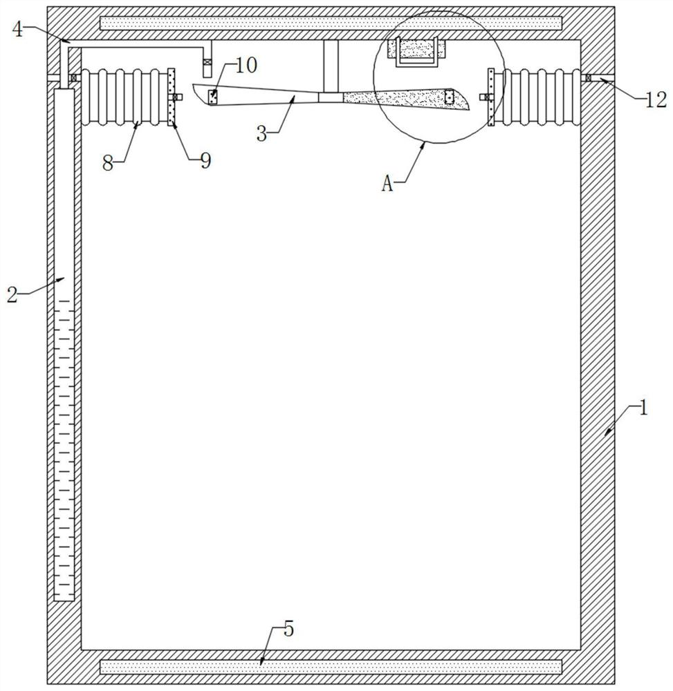
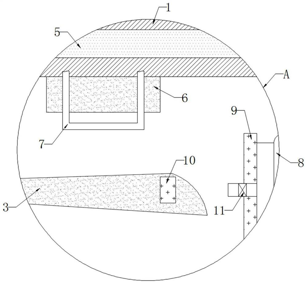
[0021] refer to Figure 1-2 , a power distribution cabinet with a self-extinguishing function, including a cabinet body 1, a liquid storage chamber 2 is opened on the side wall of the cabinet body 1, and the liquid storage chamber 2 is filled with sodium bicarbonate solution. It should be noted that the sodium bicarbonate solution It will decompose into water and carbon dioxide when heated, the reaction equation is: 2NaHCO 3 =Na 2 CO 3 +H 2 O+CO 2 ↑, the top of the cabinet body 1 is connected with a plurality of fan blades 3 through the rotation of the rotating shaft, the top of the liquid storage chamber 2 is connected to the air injection pipe 4, and a pressure relief valve is installed in the air injection pipe 4, and the air injection pipe 4 is far away from the inner wall of the liquid storage chamber 2 One end is set facing the blades of the fan blades 3, and further, a plurality of fan blades 3 blades adopt a centrifugal blade structure, so that the carbon dioxide e...

Embodiment 2

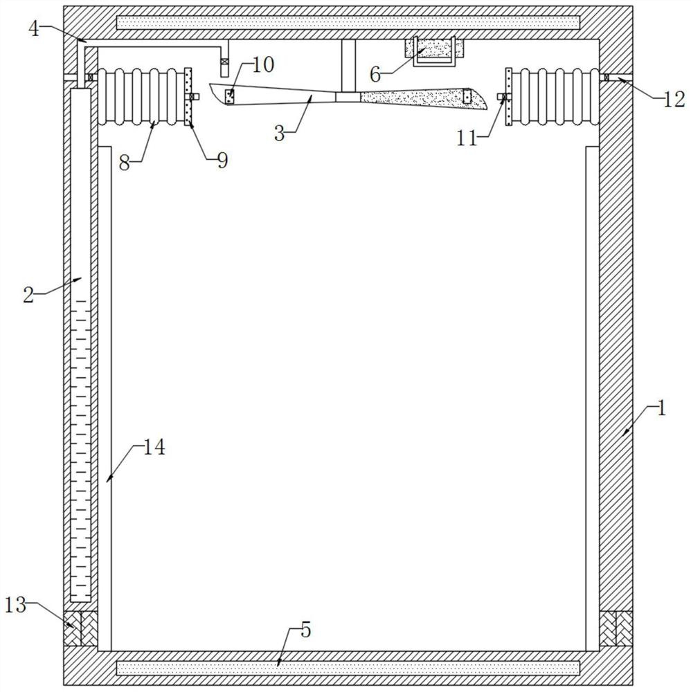
[0026] refer to image 3 , different from Embodiment 1, the lower end of the cabinet body 1 is fixedly connected with a conductor ring 13, the lead frame 7 is coupled to the conductor ring 13, the conductor ring 13 is made of two metal materials of different materials, and the conductor ring 13 is close to the cabinet One side of the inner wall of the body 1 is connected with a heat absorbing plate 14. Further, when the lead frame 7 supplies power to the conductor ring 13, the Peltier effect in the thermoelectric phenomenon occurs in the conductor ring 13, so that the conductor ring 13 is subjected to a current action. The lower end absorbs heat and the other end releases heat, so that the end of the conductor ring 13 near the inner wall of the cabinet 1 absorbs heat, and the end near the outer wall of the cabinet 1 releases heat.

[0027] In this embodiment, when the induced current is generated on the lead frame 7 to supply power to the conductor ring 13, since the conductor...


PUM


Abstract

The invention discloses a power distribution cabinet with a self-extinguishing function. The cabinet comprises a cabinet body, a liquid storage cavity is formed in the side wall of the cabinet body; the top in the cabinet body is rotatably connected with a plurality of fan blades through a rotating shaft, the top in the liquid storage cavity is connected with a gas ejector pipe, a pressure releasevalve is installed in the gas ejector pipe, the end, away from the inner wall of the liquid storage cavity, of the gas ejector pipe is right opposite to blades of the fan blades, and the bottom and the inner top in the cabinet body are symmetrically and fixedly connected with two electromagnetic plates with opposite poles. Carbon dioxide gas generated by heating a sodium bicarbonate solution is sprayed out from the gas ejector pipe; the fan blades are driven to rotate quickly while the concentration of carbon dioxide in the cabinet body is increased; due to the fact that the oxygen has the paramagnetism, the oxygen in the cabinet body moves towards the upper half portion of the cabinet body, the concentration of the oxygen in the lower half portion of the cabinet body is reduced, and fireon electronic elements located on the lower half portion of the cabinet body is restrained.

Description

technical field [0001] The invention relates to the technical field of electrical equipment, in particular to a power distribution cabinet with a self-extinguishing function. Background technique [0002] The power distribution cabinet is a power distribution device that assembles components such as switchgear, measuring instruments, protective appliances and auxiliary equipment in a closed metal cabinet. [0003] Since the power distribution cabinet is the source of power consumption control for multiple devices, the power distribution cabinet often works under high load, which makes the temperature inside the power distribution cabinet very high, especially in high temperature weather such as summer, the temperature inside the power distribution cabinet will drop. In order to maintain the dust-proof effect of its internal components, the current power distribution cabinet makes less heat dissipation in the power distribution cabinet, and when the temperature in the power d...

Claims


Application Information

Patent Timeline
IPC IPC(8): H02B1/30H02B1/28A62C3/16A62C37/11F25B21/02
CPCA62C3/16A62C37/11F25B21/02F25B2321/0251H02B1/28H02B1/30
Inventor 刘晓芳陈明伟
Owner 刘晓芳
Why Eureka
Try Eureka