
Stator short-distance separation type motor structure

A motor structure, separate technology, applied in the direction of the motor, magnetic circuit shape/pattern/structure, winding conductor shape/pattern/structure, etc., can solve the problems of weakening the output torque and unfavorable stable operation of the rotor.

Pending Publication Date: 2020-10-20
HUAIYIN INSTITUTE OF TECHNOLOGY
View PDF0 Cites 0 Cited by
  • Summary
  • Abstract
  • Description
  • Claims
  • Application Information

AI Technical Summary

Problems solved by technology

[0005] However, in conventional stator partitioned permanent magnet motors, the partitioned stators where the permanent magnets and armature windings are located are placed inside and outside the rotor respectively, and the intermediate rotor can only be connected to the shaft through one side of the rotor bracket, which is not conducive to the stable operation of the rotor. Especially in high-speed and high-torque operating occasions; and because there are two air gaps between the stator and the rotor in the two partitions, compared with the original single-air-gap permanent magnet flux switching motor, its no-load air-gap flux density and equal current The output torque under load is weakened

Method used


Image

  • Stator short-distance separation type motor structure
  • Stator short-distance separation type motor structure
  • Stator short-distance separation type motor structure

Examples


Embodiment Construction

[0026] The present invention will be described in detail below in conjunction with the accompanying drawings.

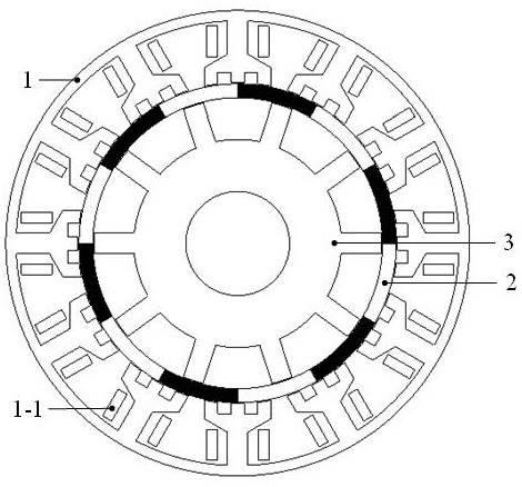
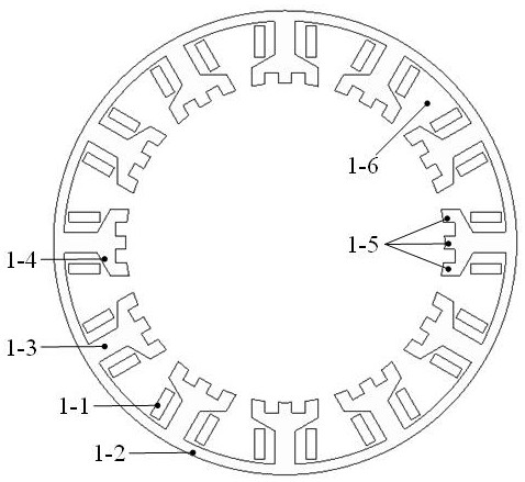
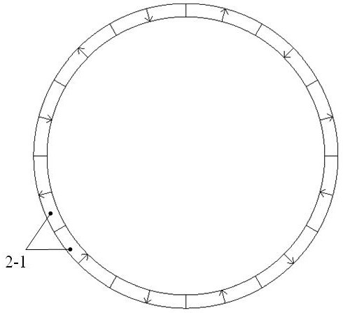
[0027] by Figure 1-Figure 4 The 3-phase outer zone stator with 12 slots / inner zone stator with 12 poles / rotor with 10 poles stator short-distance separated motor is shown as an example to specifically illustrate the technical solution of the present invention.

[0028] Motor of the present invention such as figure 1 As shown, it includes a rotor 3 arranged concentrically, an inner zone stator 2 surrounding the rotor 3 and an outer zone stator 1 surrounding the inner zone stator 2 .

[0029] An outer air gap is set between the outer zone stator 1 and the inner zone stator 2 , and an inner air gap is set between the inner zone stator 2 and the rotor 3 . The outer zone stator 1 includes the outer zone stator core and the concentrated armature winding 1-1 arranged on the outer zone stator core. The inner zone stator 2 is circular and is composed of radially alternatel...


PUM


Abstract

The invention relates to the technical field of motors, and discloses a stator short-distance separation type motor structure. The structure comprises a rotor, an inner region stator and an outer region stator which are concentrically arranged, an outer air gap is formed between the outer area stator and the inner area stator, and an inner air gap is formed between the inner area stator and the rotor. The outer area stator comprises an outer area stator iron core and a centralized armature winding arranged on the outer-area stator iron core, the inner area stator is composed of permanent magnets which are magnetized alternately in the radial direction, and the rotor is composed of a rotor yoke and rotor teeth protruding out of the rotor yoke. The inner area stator and the outer area statorare fixedly connected with the motor shell, and the rotor is fixedly connected with a rotating shaft of the motor. Compared with the prior art, on the basis of a conventional stator double-subarea motor structure, a stator short-distance separation type structure is adopted, a multi-tooth structure is adopted in each magnetic pole of the outer area stator, and a radial alternate magnetizing permanent magnet structure is adopted on the inner area stator, so that the air gap flux density and the torque density of the stator subarea motor are improved.

Description

technical field [0001] The invention relates to the technical field of motor body design, in particular to a stator short-distance separated motor structure for an electric vehicle. Background technique [0002] As a key component of electric vehicles, the performance of electric motors has a significant impact on the entire drive system. According to the application characteristics of electric vehicles, the problems to be solved in the prior art are: 1. The motor has a relatively large torque output capability; 2. The motor has relatively high reliability. [0003] At present, permanent magnet flux switching motors have attracted attention due to their high torque density, high efficiency, and highly robust rotor structure. This structure is essentially a stator permanent magnet motor. There are no windings and permanent magnets on the rotor, and the windings and permanent magnets are located on the stator. Due to the magnetism effect of the permanent magnets on the stator...

Claims


Application Information

Patent Timeline
IPC IPC(8): H02K16/04H02K3/28H02K1/14H02K1/16H02K1/17H02K1/24
CPCH02K1/146H02K1/165H02K1/17H02K1/24H02K3/28H02K16/04H02K2201/03H02K2213/03Y02T10/64
Inventor 莫丽红郑刚旭高洁刘保连张涛鲁庆叶小婷
Owner HUAIYIN INSTITUTE OF TECHNOLOGY
Learn More