
PCB assembly, LED module and LED display screen

A technology of LED modules and PCB boards, applied in printed circuit components, safety devices for installation boards, instruments, etc., can solve problems such as increased production costs, difficult removal of screw heads, scrapped PCB boards, etc.

Pending Publication Date: 2020-10-20
吉安市木林森光电显示有限公司
View PDF3 Cites 1 Cited by
  • Summary
  • Abstract
  • Description
  • Claims
  • Application Information

AI Technical Summary

Problems solved by technology

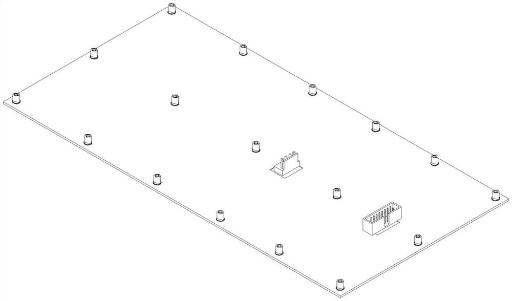
This structure is currently used in small-pitch LED displays, but due to the material of the PCB, the strength of the drilled holes for locking the screws is not enough, the screw teeth cannot meet the standard of ordinary screws, and the screw specifications are relatively small and the strength is relatively low. Affected by poor factors, this method of back-locking screws has many defects, which also makes the reliability of the product insufficient; at the same time, in the process of production and maintenance, it often occurs that the screws are broken and left on the PCB board. In this case, it is difficult to remove the broken screw head, which makes the product defective and seriously causes the PCB board to be scrapped
In view of this situation, in order to improve the reliability, a structure of welding copper pillars on the PCB has appeared. This structure can solve the problem of screw teeth breaking, but the cost will increase accordingly. With the development of mechanical equipment , With the improvement of LED display automation, this structure has defects in the automation process. Auxiliary materials must be added to realize the soldering of copper columns to the PCB board. At the same time, positioning holes must be added to the copper columns for positioning on the PCB board. Therefore Reduced production efficiency, increased risk of failure, increased production costs
[0003] In the existing LED display module, the copper pillars lock the PCB board. Since the copper pillars are all cylindrical and welded on the PCB, holes must be drilled on the PCB for the positioning of the copper pillars; after welding the copper pillars, lock the screws The torque is relatively small, and the copper post and the pad may fall off after locking the screw; due to the limitation of the equipment in the process of welding the copper post, the manipulator needs auxiliary materials to pick up the copper post with the screw hole, which increases the Cost of production

Method used


Image

  • PCB assembly, LED module and LED display screen
  • PCB assembly, LED module and LED display screen
  • PCB assembly, LED module and LED display screen

Examples


Embodiment Construction

[0027] It should be noted that, in the case of no conflict, the embodiments in the present application and the features in the embodiments can be combined with each other; the technical solutions in the embodiments of the present invention will be described below in conjunction with the drawings in the embodiments of the present invention Clearly and completely described, it is obvious that the described embodiments are only some of the embodiments of the present invention, not all of them. Based on the embodiments of the present invention, all other embodiments obtained by persons of ordinary skill in the art without making creative efforts belong to the protection scope of the present invention.

[0028] In the description of the present invention, it should be understood that the orientation or positional relationship indicated by the terms "upper", "lower", "front", "rear", "left" and "right" are based on those shown in the accompanying drawings. Orientation or positional ...


PUM


Abstract

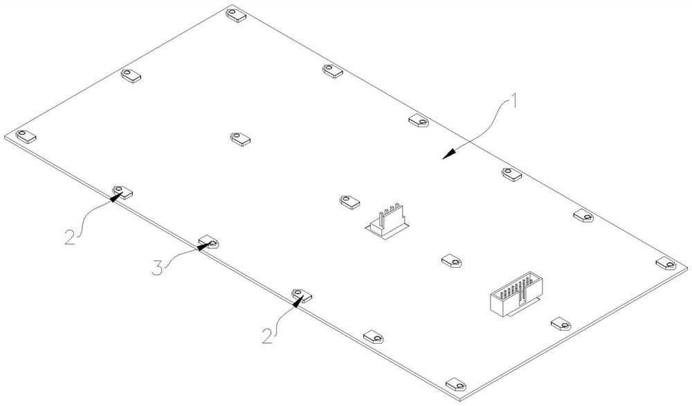
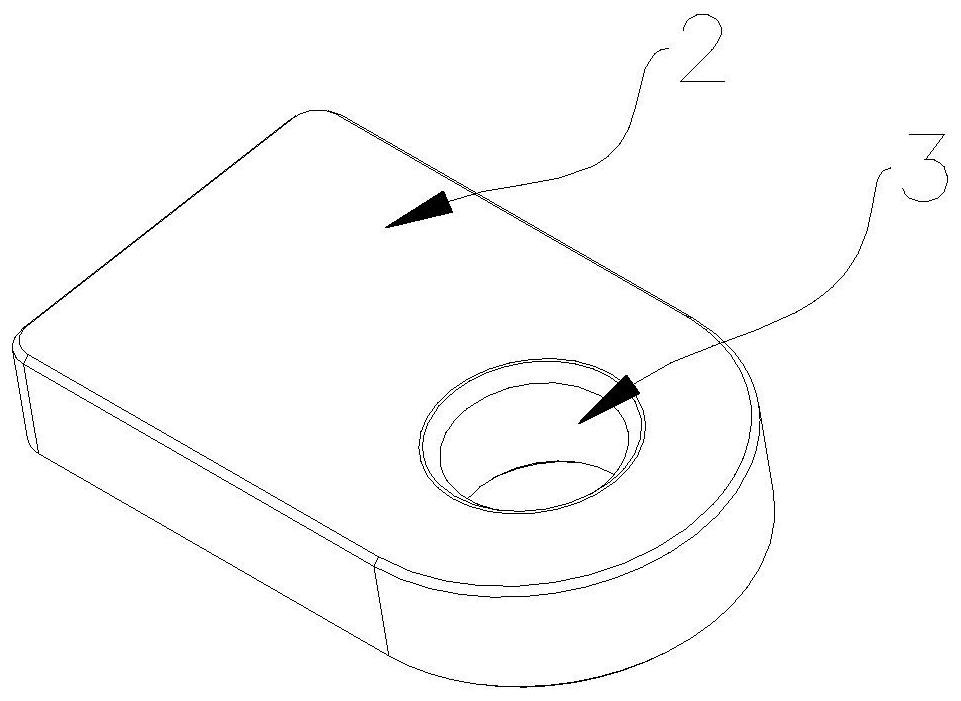
The invention discloses a PCB assembly. The PCB assembly comprises a PCB and a plurality of connecting pieces, wherein the plurality of connecting pieces are arranged on the PCB at intervals, the connecting pieces are flat, and one side, far away from the PCB, of each connecting piece is provided with a mounting part used for being connected with the outside. Holes do not need to be formed in thePCB, the cost is saved, and meanwhile more space is reserved for a PCB circuit. The overall thickness of the LED module is reduced, the LED display screen is ultrathin, and the LED display screen is more suitable for automatic production.

Description

technical field [0001] The invention relates to the technical field of LEDs, in particular to a PCB board assembly, an LED module and an LED display screen. Background technique [0002] At this stage, with the continuous advancement of technology, LED display modules have developed from the traditional PCB board + bottom case combination to two combinations of PCB board + bottom case module and PCB board module without bottom case. The LED display screen is constantly developing towards the direction of small pitch, high quality, ultra-thin, fast splicing, fast installation and disassembly, and low cost; the initial LED display PCB boards are locked from the direction of the lamp surface, but with the dot pitch The shrinkage of the lamp surface and the higher and higher requirements for the lamp surface, the direction locking screw of the lamp surface has defects, which cannot meet the corresponding requirements. Therefore, there is a structure in which the PCB board is pu...

Claims


Application Information

Patent Timeline
IPC IPC(8): H05K1/02G09F9/33H05K7/14
CPCH05K1/02G09F9/33H05K7/1417
Inventor 刘垣贤李承光高治亮
Owner 吉安市木林森光电显示有限公司
Learn More