
Built-in chemoradiotherapy pump for oncology department

A radiochemotherapy and implantation technology, applied in the field of medical devices, can solve problems such as mediocre effect, easy to affect the effect of treatment, poor functionality, etc.

Inactive Publication Date: 2020-10-23
杜恒吏
View PDF1 Cites 2 Cited by
  • Summary
  • Abstract
  • Description
  • Claims
  • Application Information

AI Technical Summary

Problems solved by technology

[0002] The implantable chemoradiotherapy pump is a device that uses a micropump to discharge chemoradiotherapy drugs regularly and quantitatively under program control. Compared with traditional chemoradiotherapy methods, the use of chemoradiotherapy pumps can reduce the pain of patients and enhance the concentration of local drugs in the tumor Simultaneous treatment of radiopharmaceuticals and chemotherapeutic drugs can improve the curative effect of some tumors. The patent application number 201621470438.7 proposes an implantable chemoradiotherapy pump for oncology. It adopts double-layer drug capsules to effectively prevent The radiopharmaceutical outlet and the chemotherapeutic drug outlet are bonded to the muscle tissue after implantation, which is convenient for subsequent use, but their simple structure leads to poor functionality, and the timing and quantitative control of drug delivery is generally effective. Able to precisely control the amount and rate of feeding, which can easily affect the effect of treatment

Method used


Image

  • Built-in chemoradiotherapy pump for oncology department
  • Built-in chemoradiotherapy pump for oncology department
  • Built-in chemoradiotherapy pump for oncology department

Examples


Embodiment 1

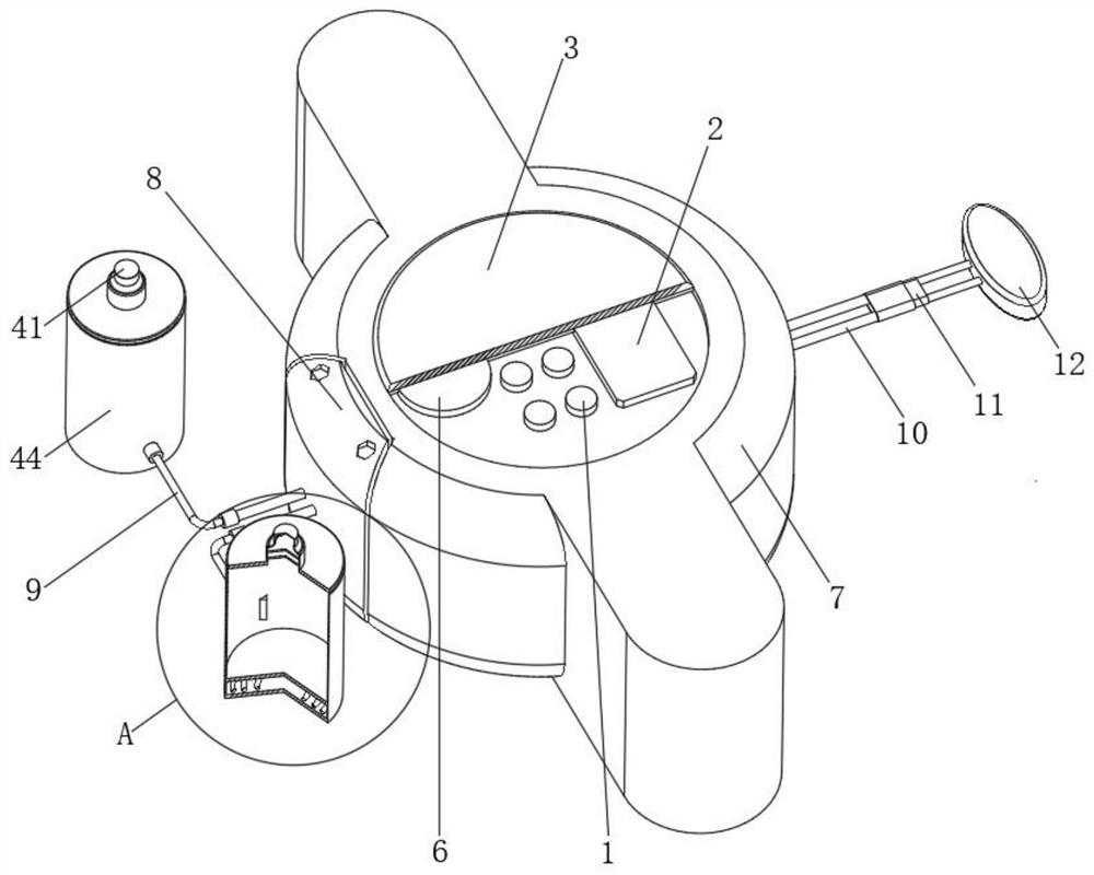
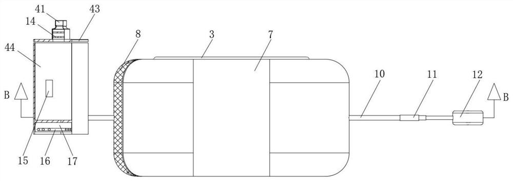
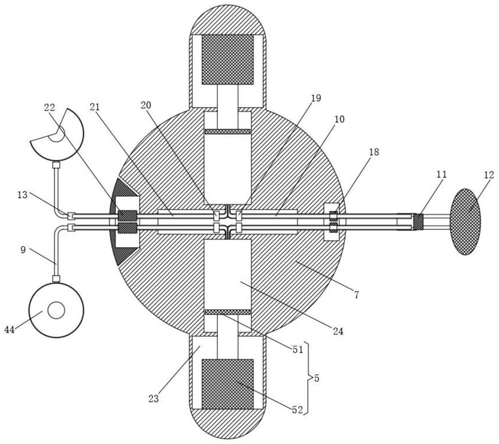
[0028] An implantable chemoradiotherapy pump for oncology, comprising a casing 7, a drug storage tank 4, a drug infusion device 5 and a drug bag 12;

[0029] Housing 7: It is provided with a liquid medicine chamber 24 and an electrical chamber 23 inside, a partition is left between the liquid medicine chamber 24 and the electrical chamber 23, the liquid medicine chamber 24 is used for quantitative liquid medicine, and the electrical chamber 23 is used for The electric push rod 52 is installed, and a groove is opened on the top of the housing 7, and a timer 6 and an indicator light 1 are installed in the groove. The timer 6 can preset the time to achieve the timing function, and the indicator light 1 is used for indicating the operating status of the instrument;

[0030] Drug storage tank 4: it has two, one is a radiotherapy drug tank for placing radiotherapy drugs, and the other is a chemotherapy drug tank for placing chemotherapy drugs. The bottom end of the drug storage tank...

Embodiment 2

[0035] The difference between this embodiment and Embodiment 1 is that it also includes a diaphragm 14, which is provided with two groups, and is fixed on the inner wall of the feed nozzle 42 in parallel. , through the diaphragm 14, the interior can be guaranteed to be in a sterile environment, and the therapeutic effect of the medicine will not be affected by external factors. It also includes a temperature sensor 15 and an electromagnetic induction coil 16. The temperature sensor 15 is fixed on the inner wall of the tank body 44 and can detect The temperature of the medicine, the bottom of the tank body 44 is provided with a heating chamber 17, the electromagnetic induction coil 16 is installed in the heating chamber 17, its input end is electrically connected to the output end of the single-chip microcomputer 2, and the output end of the temperature sensor 15 is electrically connected to the single-chip microcomputer 2 inputs.

Embodiment 3

[0037] The difference between this embodiment and the first embodiment is that it also includes a filter 22, the filter 22 is located at the end of the medicine feeding tube 9, and is located inside the housing 7, and its end communicates with the drug delivery tube 21, which consists of multiple groups It is composed of a filter net, which can filter the impurities and residues in the medicine, and also includes a splicing block 8, which is fixed on the side of the housing 7 by screws, and the filter 22 is installed in the splicing block 8, which is convenient to use The inner filter 22 is replaced and cleaned, and the glass cover 3 is also included. The glass cover 3 is snapped into the groove at the top of the housing 7. The glass cover 3 can provide protection for the timer 6 and the single-chip microcomputer 2.

[0038]When in use: unscrew the two sealing caps 41, inject radiotherapy drugs and chemotherapy drugs into the two drug storage tanks 4 with syringes, the telescop...


PUM


Abstract

The invention discloses a built-in chemoradiotherapy pump for the oncology department. The chemoradiotherapy pump comprises a shell, medicine storage tanks, a medicine conveying device and a medicinebag. The shell is internally provided with a liquid medicine chamber and an electric appliance chamber, a partition plate is reserved between the liquid medicine chamber and the electric appliance chamber, a groove is formed in the top end of the shell, and a timer and an indicator lamp are installed in the groove; the number of the medicine storage tanks is two, one medicine storage tank is a radiotherapy medicine tank, the other is a chemotherapy medicine tank, the bottom end of each medicine storage tank is connected to a medicine inlet pipe, the end of the medicine inlet pipe is communicated with the liquid medicine chamber through a medicine conveying pipe, an opening and closing valve is arranged on the side face of the medicine inlet pipe, and a second one-way valve is arranged on the medicine conveying pipe; and the medicine conveying device comprises an electric push rod and a piston plate, the electric push rod is fixed in the electric appliance chamber, an output shaft of the electric push rod is in sliding connection with the partition plate between the electric appliance chamber and the liquid medicine chamber, and the end of the output shaft is connected to the pistonplate. The chemoradiotherapy pump is high in functionality and capable of accurately controlling the conveying amount and conveying efficiency of medicines.

Description

technical field [0001] The invention relates to the technical field of medical devices, in particular to an implantable chemoradiotherapy pump for oncology. Background technique [0002] The implantable chemoradiotherapy pump is a device that uses a micropump to discharge chemoradiotherapy drugs regularly and quantitatively under program control. Compared with traditional chemoradiotherapy methods, the use of chemoradiotherapy pumps can reduce the pain of patients and enhance the concentration of local drugs in the tumor Simultaneous treatment of radiopharmaceuticals and chemotherapeutic drugs can improve the curative effect of some tumors. The patent application number 201621470438.7 proposes an implantable chemoradiotherapy pump for oncology. It adopts double-layer drug capsules to effectively prevent The radiopharmaceutical outlet and the chemotherapeutic drug outlet are bonded to the muscle tissue after implantation, which is convenient for subsequent use, but their simp...

Claims


Application Information

Patent Timeline
Patent Type & Authority Applications(China)
IPC IPC(8): A61M5/142A61M36/06A61M31/00
CPCA61M5/142A61M31/00A61N5/1007A61N5/1014
Inventor 杜恒吏任洪杰
Owner 杜恒吏
Learn More