
Double-layer oil tank rotary welding mechanism

A spin welding, double-layer oil tank technology, applied in welding equipment, welding equipment, auxiliary welding equipment, etc., can solve problems such as inability to weld cylindrical weldments, weld fractures, etc.

Inactive Publication Date: 2020-10-23
湖北天海石油集团环保科技有限公司
View PDF0 Cites 0 Cited by
  • Summary
  • Abstract
  • Description
  • Claims
  • Application Information

AI Technical Summary

Problems solved by technology

[0004] The main purpose of the present invention is to provide a rotary welding mechanism for double-layer oil tanks. By adding its corresponding functional structure and effectively matching the use environment and usage requirements, it can effectively solve the problem that existing rotary welding machines cannot handle different volumes of cylindrical When welding the weldment, when welding the cylindrical weldment with too large volume, the instability of the two weldments during the welding process may cause problems such as fracture of the uncooled weld

Method used


Image

  • Double-layer oil tank rotary welding mechanism
  • Double-layer oil tank rotary welding mechanism
  • Double-layer oil tank rotary welding mechanism

Examples


Embodiment 1

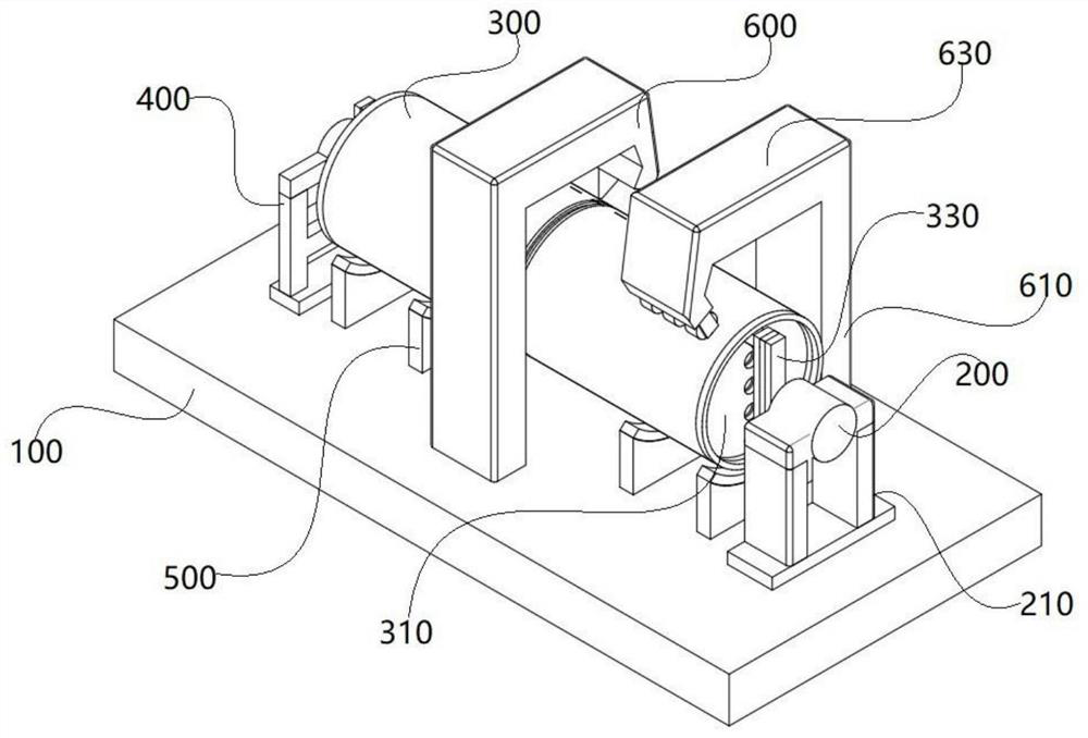
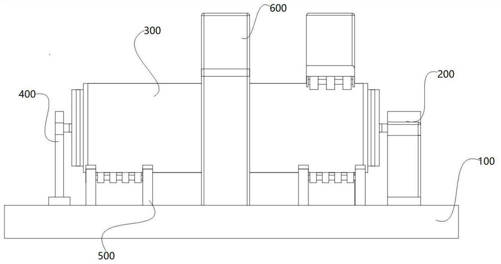
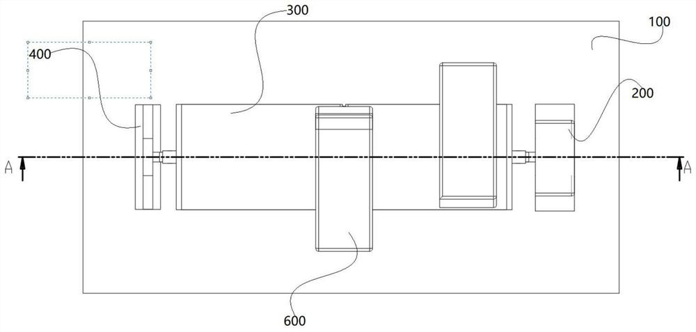
[0023] Please refer to figure 1 As shown in -4, the present invention is a double-layer oil tank rotary welding mechanism, including a fixed plate 100, a motor 200, an oil tank 300, an oil tank rotary table 400, a welding fixture 500 and an electric welding machine 600, and the motor 200 includes a motor body and The motor bracket 210, the lower surface of the motor bracket 210 is welded to the upper surface of the fixed plate 100, the motor body one surface is connected with the motor bracket 210 through threaded screw holes, the oil tank 300 includes the oil tank body and the rotating tray 310, the oil tank body is a hollow structure, Several rotating trays 310 are installed inside the oil tank body, the lower surface of the oil tank rotating table 400 is welded to the upper surface of the fixed plate 100, the lower surface of the fixed plate 100 is provided with a plurality of first installation holes, and the lower surface of the plurality of welding fixtures 500 is respect...

Embodiment 2

[0030] Please refer to figure 1 As shown in -4, the present invention is a double-layer oil tank rotary welding mechanism, wherein the model of the motor 200 is Y2. Two fixed rods 320 are positioned between the trays 310 to ensure that the two oil tanks 300 to be welded remain relatively still during the welding process. During the welding process, the motor 200 drives the oil tank 300 to rotate, and the electric welding machine 600 follows the circular weld seam Welding is performed, and the electrode 630 and the oil tank 300 are kept in a connected state through the provided conductive wheel.


PUM


Abstract

The invention discloses a double-layer oil tank rotary welding mechanism, and relates to the technical field of rotary welding. The double-layer oil tank rotary welding mechanism comprises a fixed plate, a motor, oil tanks, an oil tank rotary table, welding clamps and an electric welding machine, wherein the motor comprises a motor body and a motor support, the lower surface of the motor support is welded to the upper surface of the fixed plate, one surface of the motor body is connected with the motor support through threaded holes, a plurality of first mounting holes are formed in the lowersurface of the fixed plate, and the lower surfaces of a plurality of welding clamps are connected with the plurality of first mounting holes respectively. According to the double-layer oil tank rotarywelding mechanism disclosed by the invention, through arrangement of a rotary tray, a fixed rod, a first rotary support and a second rotary support, the synchronous rotation of the oil tanks at two sides can be guaranteed, and stability of weldments in the welding process is guaranteed; through arrangement of clamp rollers, the oil tanks can be supported and stabilized, friction between the oil tanks and the supports can be reduced, the weldments are kept stable in the welding process, and the noise generated by friction is reduced.

Description

technical field [0001] The invention relates to the field of welding technology, in particular to a rotary welding mechanism for a double-layer oil tank. Background technique [0002] Welding technology is widely used in industrial production, but when the shape of the weldment is not a flat plate but a regular cylinder, the common automatic welding machine cannot be used, the labor efficiency is too low and it is difficult to process the large cylindrical shape. Therefore, it is very necessary to design a reasonable welding method. [0003] The existing rotary welding machine cannot weld cylindrical weldments with different volumes. When welding cylindrical weldments with too large volume, the uncooled weld may break due to the instability of the two weldments during the welding process. For this reason, we propose a double-layer oil tank rotary welding mechanism. Contents of the invention [0004] The main purpose of the present invention is to provide a rotary welding...

Claims


Application Information

Patent Timeline
Patent Type & Authority Applications(China)
IPC IPC(8): B23K37/053B23K37/02B23K9/028B23K101/12
CPCB23K9/028B23K37/02B23K37/0538B23K2101/125
Inventor 徐文成李荣清黄鑫杨成新
Owner 湖北天海石油集团环保科技有限公司
Learn More