Brake fault detection method and device
A fault detection and fault technology, applied in the field of automation, can solve the problems of threatening the life safety of users and heavy manual workload
- Summary
- Abstract
- Description
- Claims
- Application Information
AI Technical Summary
Problems solved by technology
Method used
Image
Examples
Embodiment 1
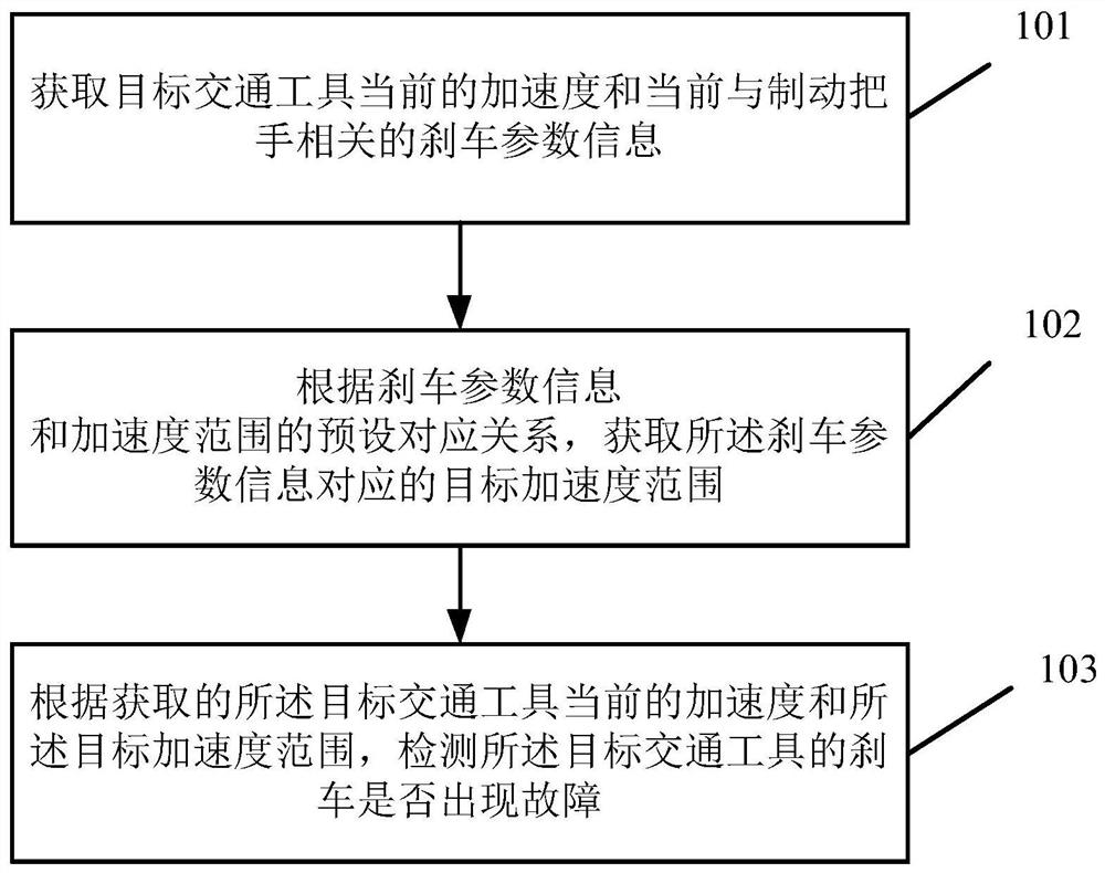
[0094] figure 1 A schematic flow chart of a brake fault detection method provided in Embodiment 1 of the present application, as shown in figure 1 As shown, the method includes the following steps:
[0095] Step 101. Obtain the current acceleration of the target vehicle and the current braking parameter information related to the brake handle.
[0096]Specifically, the vehicle may decelerate the vehicle through a braking system during driving, so as to achieve the purpose of braking. If there is a problem with the braking system, the vehicle cannot decelerate, or the vehicle can decelerate, but the deceleration trend (deceleration situation) will be abnormal compared with the normal situation, so in order to determine whether the braking system is faulty, it is necessary to judge Whether the vehicle has decelerated, and if so, it is necessary to further judge whether the deceleration trend matches the action of the braking system. For example, the greater the action range of...
Embodiment 2
[0151] Figure 6 A schematic structural diagram of a brake fault detection device provided in Embodiment 2 of the present application, as shown in Figure 6 As shown, the device includes:
[0152] The acquisition unit 61 is used to acquire the current acceleration of the target vehicle and the current braking parameter information related to the brake handle;
[0153] An acquisition unit 62, configured to acquire the target acceleration range corresponding to the current braking parameter information related to the brake handle according to the preset corresponding relationship between the braking parameter information and the acceleration range;
[0154] The detection unit 63 detects whether the brake of the target vehicle fails according to the acquired current acceleration of the target vehicle and the target acceleration range.
[0155] In a feasible implementation, the current brake parameter information related to the brake handle includes at least one of the following...
Embodiment 3
[0186] Figure 10 A schematic structural diagram of an electronic device provided in Embodiment 3 of the present application, including: a processor 1001, a storage medium 1002, and a bus 1003, and the storage medium 1002 includes such as Figure 6 In the device shown, the storage medium 1002 stores machine-readable instructions executable by the processor 1001. When the electronic device runs the above positioning method, the processor 1001 and the storage medium 1002 are connected through a bus 1003 communication, the processor 1001 executes the machine-readable instructions to perform the following steps:
[0187] Obtain the current acceleration of the target vehicle and the current braking parameter information related to the brake handle;
[0188] Acquiring the target acceleration range corresponding to the current braking parameter information related to the brake handle according to the preset corresponding relationship between the braking parameter information and the a...
PUM
 Abstract
Description
Claims
Application Information
 - R&D
- Intellectual Property
- Life Sciences
- Materials
- Tech Scout
- Unparalleled Data Quality
- Higher Quality Content
- 60% Fewer Hallucinations
Browse by: Latest US Patents, China's latest patents, Technical Efficacy Thesaurus, Application Domain, Technology Topic, Popular Technical Reports.
© 2025 PatSnap. All rights reserved.Legal|Privacy policy|Modern Slavery Act Transparency Statement|Sitemap|About US| Contact US: help@patsnap.com


