Eureka AIR delivers breakthrough ideas for toughest innovation challenges, trusted by R&D personnel around the world.

Ultra-large deflection flat coil without ferrite core

A ferrite core, deflection plane technology, applied in the direction of electrode devices and related components, can solve problems such as temperature rise, increase in ferrite core loss, and deterioration of core performance

Inactive Publication Date: 2003-08-13
SHANGHAI JIAO TONG UNIV
View PDF1 Cites 0 Cited by
  • Summary
  • Abstract
  • Description
  • Claims
  • Application Information

AI Technical Summary

Problems solved by technology

As the scanning frequency increases, the loss of the ferrite core will increase greatly, causing temperature rise and deteriorating the performance of the magnetic core, thereby affecting the scanning performance and causing adverse consequences.
In the 4th issue of "Color Picture Tube" magazine in 1997, Li Menghu's article "Research and Application of Magnetic Materials in DY Design" pointed out that "the scanning frequency of ultra-high resolution displays is as high as 64-128KHZ, due to the existence of hysteresis loss and residual magnetic loss , eddy current loss, and reluctance loss, so the deflection yoke often works above the normal temperature, and when the deflection current is under abnormal working conditions, these will cause the magnetization saturation effect, which will change the Fourier harmonic component of the magnetic field and cause the electron beam Convergence drift, grating distortion degradation, deflection sensitivity reduction, etc.
"At the same time, it is also pointed out that the significant feature of the high frequency loss of the ferrite core is that it will cause temperature rise, which will affect other magnetic properties, and finally affect the performance of the deflection coil.

Method used


Image

  • Ultra-large deflection flat coil without ferrite core
  • Ultra-large deflection flat coil without ferrite core
  • Ultra-large deflection flat coil without ferrite core

Examples


specific Embodiment approach

[0007] In order to better understand the technical solution of the present invention, further description will be made below in conjunction with the accompanying drawings.

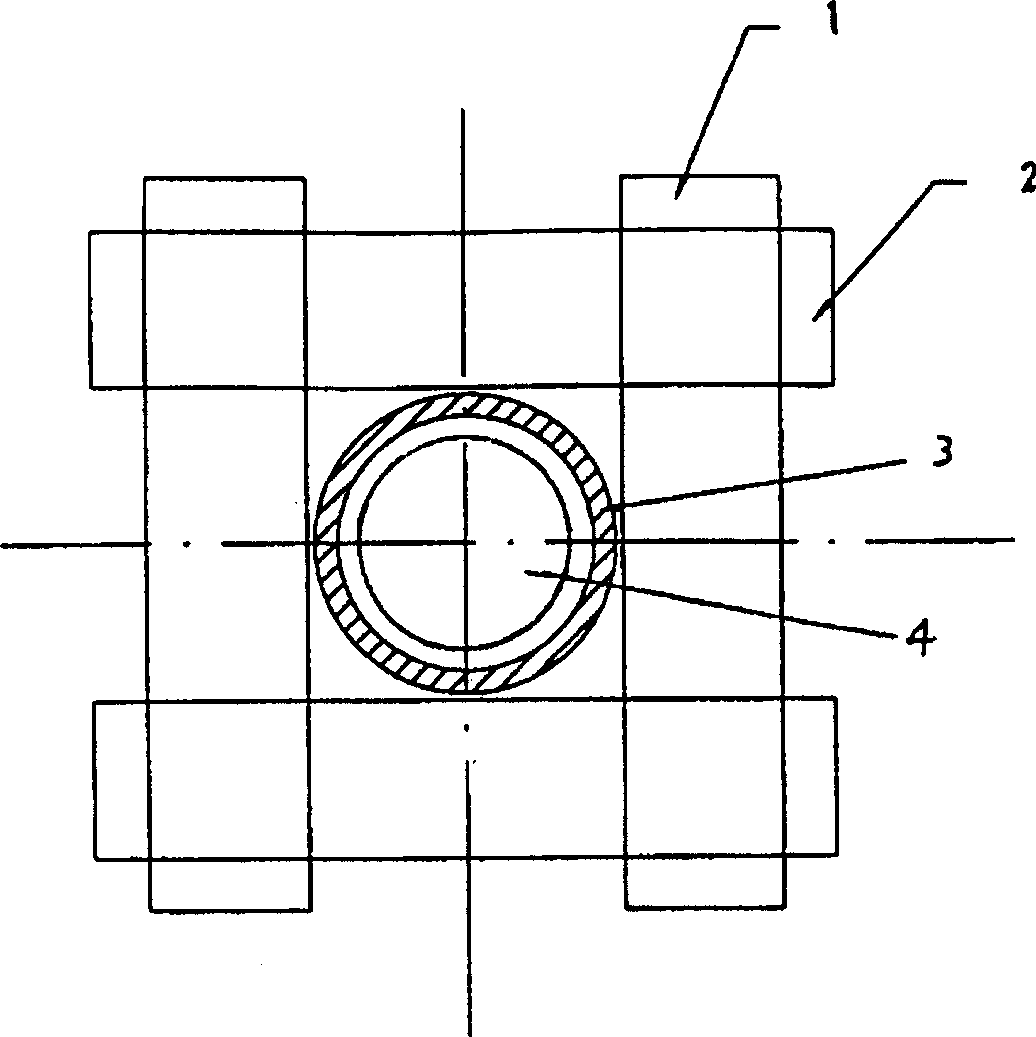
[0008] figure 1 It is a schematic diagram of the basic structure mode of the present invention.

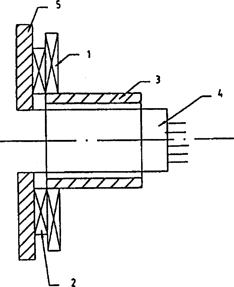
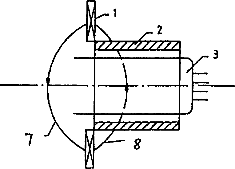
[0009] As shown in the figure, the basic structural model of the ultra-large deflection planar coil without a ferrite core includes a pair of planar rectangular frame deflection coils 1 and a pair of planar rectangular row deflection coils 2. The two pairs of deflection coils are placed perpendicular to each other on a plane. There is a magnetic shielding ring 3 perpendicular to the plane where the coils are located in the center of the two pairs of deflection coils.

[0010] The magnetic shielding ring 3 is made of high magnetic permeability material, which can be placed on the outside of the electron gun barrel neck 4, and the inner diameter of the central hole is determined by the outer diameter of the ele...


PUM


Abstract

An ultra-large-deflection flat coil without ferrite core for CRT has a pair of rectangular frame deflection coils and a pair of rectangular line deflection coils, which are perpendicularly arranged on a plane. A magnetic shielding ring perpendicular to said plane is arranged in the center. A predeflection coil can be wound on said ring as sleeve of the neck of CRT. Its advantages are large deflection angle and high deflection sensitivity.

Description

Technical field: [0001] The invention relates to a super large deflection planar coil of a picture tube, in particular to a super large deflection planar coil of a picture tube without a ferrite magnetic core, belonging to the technical field of electrical basic electrical components. Background technique: [0002] With the development of high-definition television and multimedia, picture tubes are also developing towards high-definition, large screen and flattening, and the key to flattening is to further increase the deflection angle. The neck of a traditional picture tube is cylindrical, followed by a trumpet-shaped opening, so the inner wall of the deflection coil that scans the electron beam is also made into a corresponding shape to match the outer wall of the picture tube. At present, the large-screen deflection yokes all have trumpet-shaped ferrite cores, and are tightly assembled with the line deflection and frame deflection yokes. However, when the deflection angl...

Claims


Application Information

Patent Timeline
IPC IPC(8): H01J29/76
Inventor 张可南梁国恩林书铨王妙康唐敦乙黄保麟
Owner SHANGHAI JIAO TONG UNIV
Why Eureka
Eureka Blog
Learn More