
Continuous coating furnace

A coating and connection technology, applied in the direction of liquid chemical plating, metal material coating process, coating, etc., can solve the problem of affecting product quality, the inability to achieve accurate adjustable and controllable oxygen concentration, and poor performance of the coating furnace. Standards and other issues

Active Publication Date: 2020-10-23
安徽和博自动化设备有限公司
View PDF22 Cites 0 Cited by
  • Summary
  • Abstract
  • Description
  • Claims
  • Application Information

AI Technical Summary

Problems solved by technology

[0002] The coating furnace is a kind of equipment for coating tantalum capacitors. The coating is the process of putting the tantalum capacitors impregnated with manganese nitrate solution into the furnace for multiple thermal decomposition to form a layer of manganese dioxide film. Early domestic coating furnaces are all It is imported from abroad, trying to develop domestic industrial technology, and some film furnace manufacturers have appeared in China, but the domestic self-produced film furnaces have the following problems: 1) The temperature uniformity is large, and the internal temperature Uneven; 2), the uniformity of the internal wind speed is difficult to control; 3), the concentration of oxygen content during thermal decomposition cannot be accurately adjusted and controlled, these problems make the performance of domestic film furnaces not up to standard, resulting in the coating effect of the product Failure to meet expectations, thereby affecting the quality of the product

Method used


Image

  • Continuous coating furnace
  • Continuous coating furnace
  • Continuous coating furnace

Examples


Embodiment Construction

[0033] Embodiments of the technical solutions of the present invention will be described in detail below in conjunction with the accompanying drawings. The following examples are only used to illustrate the technical solutions of the present invention more clearly, and therefore are only examples, rather than limiting the protection scope of the present invention.

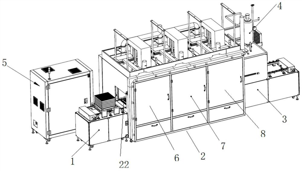
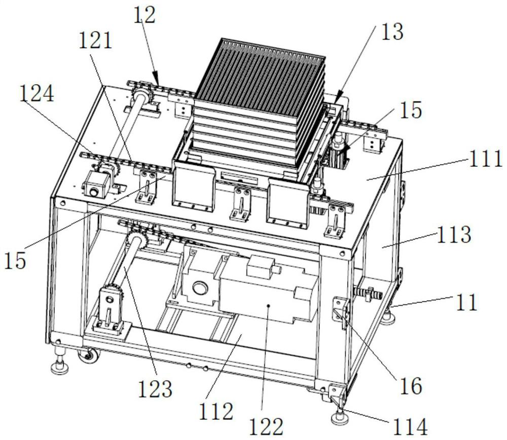
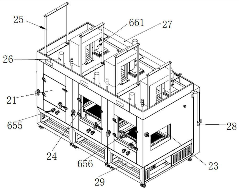
[0034] A continuous coating furnace disclosed by the present invention mainly realizes the thermal decomposition operation of the tantalum capacitor impregnated with the manganese nitrate solution, and includes automatic loading before the thermal decomposition operation and automatic unloading after the thermal decomposition. The specific structure is as follows figure 1 As shown, it includes feeding structure 1, thermal decomposition mechanism 2, cooling and unloading mechanism 3, water vapor heating mechanism 4 and electric control box 5. The feeding mechanism sends impregnated tantalum capacitors into the therma...


PUM


Abstract

The invention discloses a continuous coating furnace. The continuous coating furnace comprises a feeding structure, a thermal decomposition mechanism, a cooling and discharging mechanism, a water vapor heating mechanism and an electric cabinet; the thermal decomposition mechanism is provided with a dehydration cavity, a turnover cavity and a decomposition cavity; the feeding mechanism feeds an impregnated tantalum capacitor into the thermal decomposition mechanism; dehydration is performed through the dehydration cavity; reaction state transition is performed through the turnover cavity; the decomposition cavity performs oxidation reaction, water vapor is provided through the water vapor heating mechanism in the reaction process, and cooling and discharging are performed through the cooling and discharging mechanism after reaction. According to the continuous coating furnace, the structure in a thermal decomposition cavity is optimized, so that the internal temperature is uniform, theair speed is uniform and controllable, the oxygen content is accurately adjustable and controllable, and the coating effect is improved.

Description

technical field [0001] The invention relates to the field of coating furnaces, in particular to a continuous coating furnace. Background technique [0002] Coating furnace is a kind of equipment for coating tantalum capacitors. Coating is the process of putting tantalum capacitors impregnated with manganese nitrate solution into the furnace for multiple thermal decomposition to form a layer of manganese dioxide film. Early domestic coating furnaces are all It was imported from abroad, trying to develop domestic industrial technology, and some film furnace manufacturers have appeared in China, but the domestic self-produced film furnaces have the following problems: 1) The temperature uniformity is large, and the internal temperature Unevenness; 2), the uniformity of the internal wind speed is difficult to control; 3), the concentration of oxygen content during thermal decomposition cannot be adjusted and controlled accurately, these problems make the performance of domestic ...

Claims


Application Information

Patent Timeline
Patent Type & Authority Applications(China)
IPC IPC(8): C23C18/12
CPCC23C18/1216C23C18/1283C23C18/1241
Inventor 李永传
Owner 安徽和博自动化设备有限公司
Learn More