Novel lattice type combined shear wall

A combined shear wall and lattice structure technology, applied in the direction of walls, building components, building types, etc., can solve the problems of being unable to bear vertical loads, increasing costs, and insufficient energy consumption capacity

Pending Publication Date: 2020-10-23
上海结奕建筑咨询事务所
View PDF0 Cites 1 Cited by
  • Summary
  • Abstract
  • Description
  • Claims
  • Application Information

AI Technical Summary

Problems solved by technology

[0002] At present, prefabricated buildings are vigorously promoted in China. Traditional concrete shear walls are low in cost, but have poor seismic resistance, low ductility, and insufficient energy dissipation capacity; steel plate shear walls have good ductility, but cannot bear vertical loads, and can only bear horizontal loads. The single steel plate is in the center of the wall, and fire prevention measures are required, which increases the cost
Double steel plate shear wall, the steel tube bundle shear wall has good performance, can bear compressive bending shear load and has good seismic performance, but the steel content is high, the cost is high, and fire protection is also required, but the steel plates are on the outer edges of both sides of the wall. The fireproof structure will increase the thickness of the wall and occupy the space of the building

Method used


Image

  • Novel lattice type combined shear wall
  • Novel lattice type combined shear wall
  • Novel lattice type combined shear wall

Examples


Embodiment 1

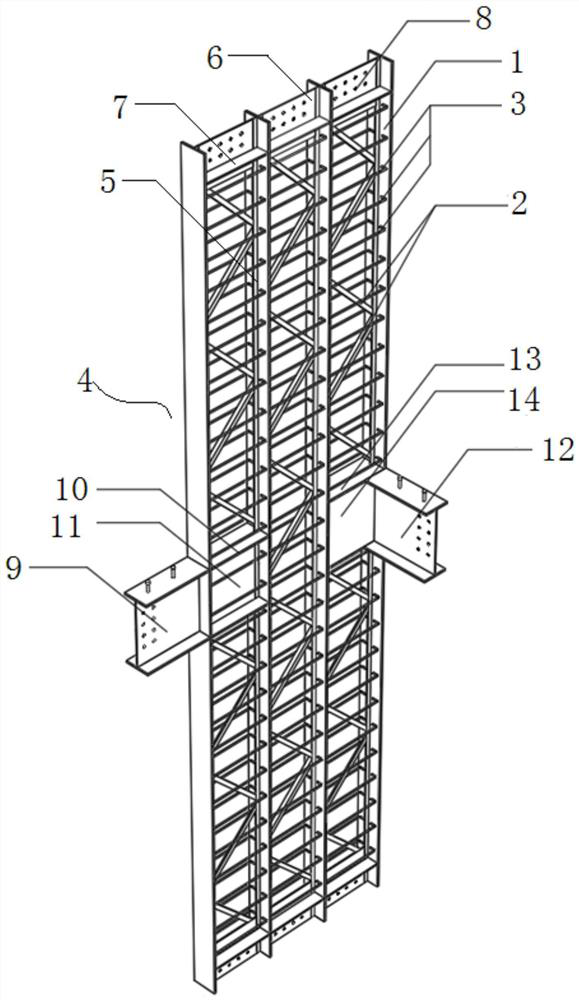
[0044] The shear wall body 4 can be prefabricated in a factory or poured on site.

[0045] Such as figure 2 As shown, when the concrete is prefabricated in the factory, the main body of the shear wall 5 is laid flat on the formwork platform or any flat site that is convenient for form removal, and the flange and the node head plate can form a lateral formwork to pour each cavity , maintenance after vibrating and smoothing, transported to the site for hoisting after leaving the factory, basically consistent with the steel structure, and can maintain a very high construction speed.

[0046] In this patent, the joint area is filled with the solid web by welding the steel plate, and the connecting bolt holes are opened. At this time, if the factory prefabricated concrete is required, the head plate needs to be welded. The head plate can be As a side form when pouring concrete, it also acts as a reinforcement for the node area. When pouring on site, it is determined whether a hea...

Embodiment 2

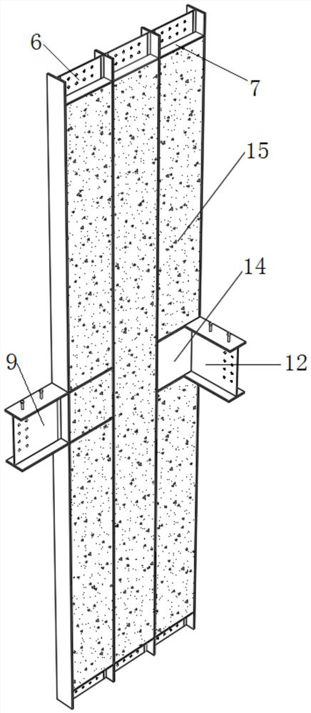
[0048] Such as Figure 3-5 As shown, when the concrete 15 is poured on site, the outer periphery of the shear wall main body 5 is covered with a wooden formwork or a reinforced expansion net 16 . A ribbed expanded mesh is preferred in this embodiment.

[0049] The ribbed expansion net 16 is an ultra-thin steel formwork densely covered with long strip holes 17, and the upper end of the rib expansion net is provided with a pouring hole 18, and the pouring hole 18 is connected with the external concrete pumping equipment through the pumping pipeline 19. 20 connection for pouring concrete 15 into the main body 4 of the shear wall.

[0050] When pouring concrete on site, ordinary wooden formwork can be used. This patent preferably has a reinforced expanded mesh, which is an ultra-thin steel formwork densely covered with fine and long strip holes. The gap of the formwork is not enough to allow the cement slurry to leak out. The hanging mesh layer as the building surface is conveni...


PUM


Abstract

The invention discloses a novel lattice type combined shear wall. The novel lattice type combined shear wall comprises T-shaped flanges, truss web members and tie bars. Every two T-shaped flanges forma set and are oppositely arranged, and the T-shaped flanges are connected together through the truss web members. Every two tie bars form a set and are horizontally welded between the two corresponding opposite T-shaped flanges. The two tie bars in each set are symmetrically welded into cavities on two sides of the corresponding T-shaped flange, two ends of each tie bar are bent and welded on thecorresponding T-shaped flange, and the plurality of sets of T-shaped flanges are welded together to form a shear wall body of a multi-grid cavity structure. The shear wall has a brand-new shear wallstructure, does not need fire prevention measures, has good seismic performance, is low in steel content, greatly saves cost, is very convenient to construct, and can be prefabricated in a factory andpoured on site.

Description

technical field [0001] The invention relates to a novel shear wall, in particular to a novel lattice type combined shear wall, which belongs to the technical field of construction engineering. Background technique [0002] At present, prefabricated buildings are vigorously promoted in China. Traditional concrete shear walls are low in cost, but have poor seismic resistance, low ductility, and insufficient energy dissipation capacity; steel plate shear walls have good ductility, but cannot bear vertical loads, and can only bear horizontal loads. The single steel plate is in the center of the wall, and fire prevention measures are required, which increases the cost. Double steel plate shear wall, the steel tube bundle shear wall has good performance, can bear compressive bending shear load and has good seismic performance, but the steel content is high, the cost is high, and fire protection is also required, but the steel plates are on the outer edges of both sides of the wall...

Claims


Application Information

Patent Timeline
Patent Type & Authority Applications(China)
IPC IPC(8): E04B2/56E04B2/58E04B2/60E04B2/62E04H9/02E04B1/94
CPCE04B1/941E04B2/56E04B2/58E04B2/60E04B2/62E04H9/021
Inventor 李杰
Owner 上海结奕建筑咨询事务所
Why Eureka
Try Eureka