Optical element surface shape measuring device and method in low-temperature environment

A technology of optical components and measuring devices, which is applied in the field of optical detection and can solve problems such as test errors

Active Publication Date: 2020-10-23
XI'AN INST OF OPTICS & FINE MECHANICS - CHINESE ACAD OF SCI
View PDF6 Cites 6 Cited by
  • Summary
  • Abstract
  • Description
  • Claims
  • Application Information

AI Technical Summary

Problems solved by technology

[0009] In order to solve the technical problem that the existing method for testing the surface shape of optical elements in a low temperature environment is limited by the caliber of the interferometer and the deformation of the vacuum container window glass will introduce test errors, the present invention provides an accurate, reliable and easy-to-operate low-temperature Apparatus and method for measuring surface shape of optical element in environment

Method used


Image

  • Optical element surface shape measuring device and method in low-temperature environment
  • Optical element surface shape measuring device and method in low-temperature environment
  • Optical element surface shape measuring device and method in low-temperature environment

Examples


Embodiment Construction

[0037] The present invention will be described in detail below in conjunction with the accompanying drawings.

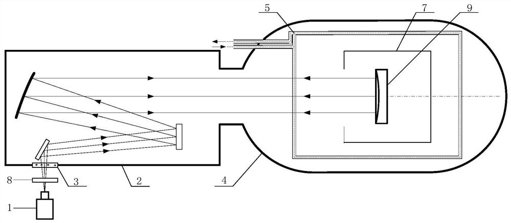
[0038] Such as figure 1 As shown, the optical element surface shape measurement device provided by the present invention includes a wavefront sensor 1, a collimator 2, and a vacuum container 4; the collimator 2 is provided with a window glass 3, and the vacuum container 4 is provided with a temperature control cover 7. A liquid nitrogen heat sink 5 is provided on the temperature control cover 7 .

[0039] The collimator 2 and the vacuum container 4 are hermetically connected to form a sealed cavity together; the wavefront sensor 1 is located outside the vacuum container 4, and its position corresponds to the window glass 3 of the vacuum container 4; In the case of a spherical surface, a compensator 8 needs to be arranged between the wavefront sensor 1 and the window glass 3 for compensating the optical path in the test optical path.

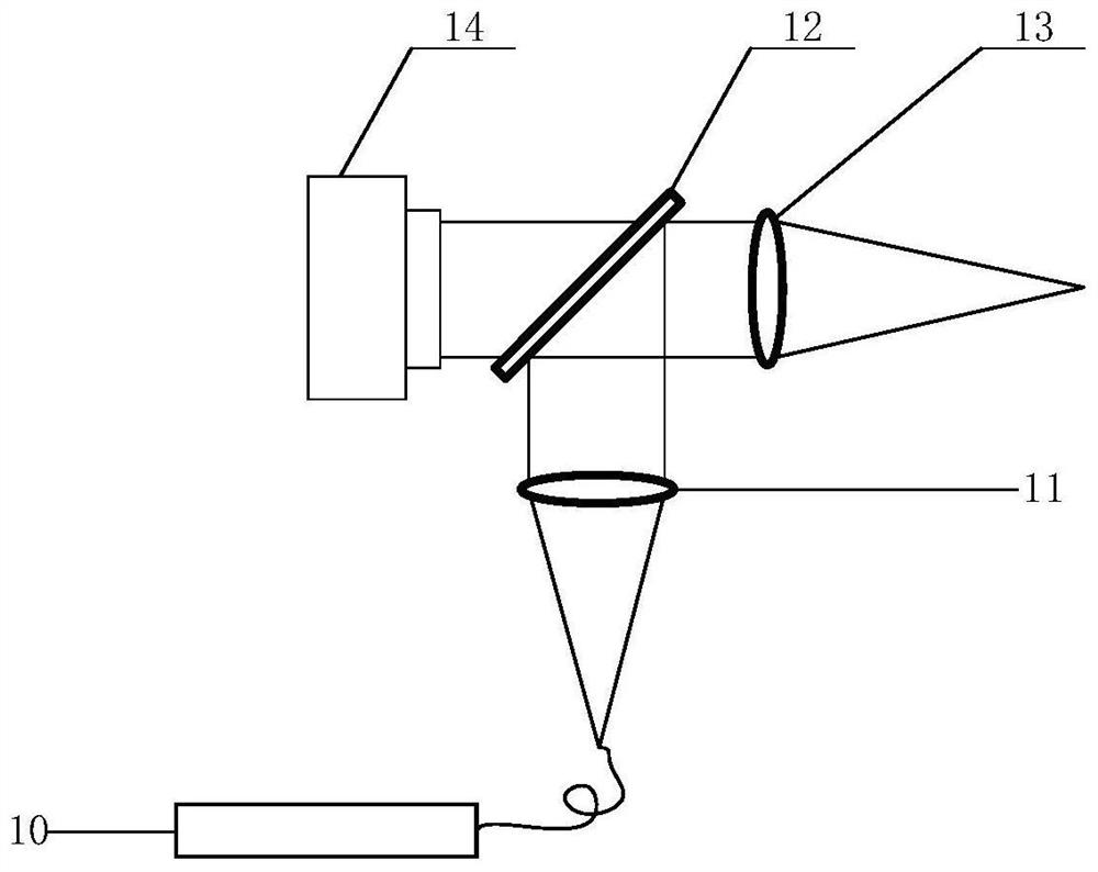
[0040] Such as figure 2 As s...


PUM


Abstract

In order to solve the technical problems that an existing method for testing the surface shape of an optical element in a low-temperature environment is limited by the caliber of an interferometer andtest errors can be caused by deformation of window glass of a vacuum container, the invention provides an optical element surface shape measuring device and method in low-temperature environment, which are accurate, reliable and convenient to operate. The optical element surface shape measuring device comprises a wavefront sensor, a collimator and a vacuum container. Window glass is arranged on the collimator, a temperature control cover is arranged in the vacuum container, and a liquid nitrogen heat sink is arranged on the temperature control cover. The temperature control cover and the liquid nitrogen heat sink jointly provide a low-temperature environment required by the design for the to-be-tested optical element; the collimator and the vacuum container are connected in a sealed modeto form a sealed cavity together. The wave-front sensor is positioned outside the vacuum container and corresponds to the window glass on the collimator in position; the wavefront sensor not only canoutput light beams, but also can detect the light beams emitted from the window glass. Compared with a traditional interference measurement method, the device and the method are high in airflow resistance and vibration resistance.

Description

technical field [0001] The invention belongs to the field of optical detection, and relates to a device and method for measuring the surface shape of an optical element in a low-temperature environment. Background technique [0002] Infrared optical systems are widely used in fields such as astronomical observation, earth observation, and weak target detection. Especially in the field of astronomical observation, due to the low temperature of stars and interstellar medium, the radiation is mainly light waves in the infrared band. The signal-to-noise ratio of the currently used infrared astronomical detector system is mainly limited by the background radiation, and the most important radiation comes from the radiation of the detector itself. In order to improve the signal-to-noise ratio of the system, it is very important to control the radiation of the detector itself. A feasible method is to reduce the temperature of the optical system itself to reduce its own background r...

Claims


Application Information

Patent Timeline
Patent Type & Authority Applications(China)
IPC IPC(8): G01B11/24
CPCG01B11/24
Inventor 鄂可伟赵建科周艳田留德王亚军薛勋李晶刘尚阔
Owner XI'AN INST OF OPTICS & FINE MECHANICS - CHINESE ACAD OF SCI
Why Eureka
Try Eureka