Beam forming method combined with array antenna unit pattern

An antenna pattern and array antenna technology, applied in diversity/multi-antenna systems, electrical components, radio transmission systems, etc., can solve the problems of performance degradation, beam performance degradation, and weakening of antenna amplitudes

Active Publication Date: 2020-10-23
10TH RES INST OF CETC
View PDF7 Cites 3 Cited by
  • Summary
  • Abstract
  • Description
  • Claims
  • Application Information

AI Technical Summary

Problems solved by technology

[0005] The present invention aims at the problem that the beam performance of the array antenna beamforming method is degraded when the pattern of the array antenna unit is inconsisten...

Method used


Image

  • Beam forming method combined with array antenna unit pattern
  • Beam forming method combined with array antenna unit pattern
  • Beam forming method combined with array antenna unit pattern

Examples


Embodiment Construction

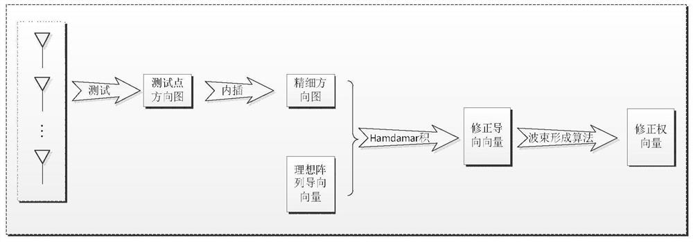
[0017] refer to figure 1 . According to the present invention, for the array antenna, each antenna unit of the array antenna is tested for the pattern, and the pattern database of the array antenna is established according to the pattern of the antenna test point; The interpolation method is used to obtain the fine pattern of the response of the array antenna in a direction with a higher degree of discretization; the interpolation of the measured antenna pattern is carried out to obtain a more detailed pattern of the array antenna, and the steering vector of the ideal array antenna is obtained by using the antenna pattern. The correction method is to perform the Hadamard product of the fine pattern obtained by interpolation and the ideal antenna steering vector, so as to obtain the revised steering vector; then based on the modified steering vector expression, use the linear constraint minimum variance LCMV and other algorithms to obtain Beamforming weight vector to implement...


PUM


Abstract

The invention provides a beam forming method combined with an antenna array element directional diagram. By utilizing the beam forming method, the performance when the directional diagrams of beam forming array antenna units are inconsistent can be enhanced. According to the technical scheme, the method comprises the following steps: for an array antenna, carrying out directional diagram test on each antenna unit of the array antenna, and establishing an array antenna directional diagram database according to an antenna test point directional diagram; obtaining a fine directional diagram responded by the array antenna in a direction with a higher discretization degree by utilizing an antenna directional diagram database and adopting an interpolation mode of linear interpolation and splineinterpolation; carrying out interpolation on an actually measured antenna directional diagram to obtain a finer directional diagram of the array antenna, utilizing the antenna directional diagram to correct a guide vector of an ideal array antenna, wherein the correction method comprises the following steps: carrying out Hadamard product on the fine directional diagram obtained by interpolation and the guide vector of the ideal array antenna to obtain a corrected guide vector; and then obtaining a beam forming weight vector by using algorithms such as a linear constraint minimum variance LCMVand the like.

Description

technical field [0001] The present invention relates to a beam forming method widely used in the fields of radar, communication, sonar, earthquake, and astronomy, etc., and in particular relates to a beam forming method of combined array antenna unit pattern. Background technique [0002] Array signal processing is an important branch of signal processing. Array signal processing refers to the processing of signals induced by array elements. Array signal processing can be divided into two branches: direction of arrival (DOA) estimation and spatial filtering. The main issues of array signal processing include: spatial spectrum estimation for super-resolution estimation of the distribution of the direction of arrival of space signals; beamforming techniques for the main lobe of the array pattern to point in the desired direction; aligning the null point of the antenna to all Null formation technique for interference direction. The antenna pattern is a graph that characteriz...

Claims


Application Information

Patent Timeline
IPC IPC(8): H04B7/06H04B7/08
CPCH04B7/0617H04B7/086Y02D30/70
Inventor 刘亮王亚涛黄秀琼乔文昇王立
Owner 10TH RES INST OF CETC
Why Eureka
Try Eureka