
Method and system for detecting end-to-end data transmission quality

A technology for data transmission quality and detection end, which is applied in the field of network communication and can solve the problems of discarding, many internal calling modules, and incompatibility with consumer-grade product communication products.

Active Publication Date: 2020-10-23
NANJING BESTLINK TECH CO LTD
View PDF7 Cites 3 Cited by
  • Summary
  • Abstract
  • Description
  • Claims
  • Application Information

AI Technical Summary

Problems solved by technology

The above-mentioned invention needs to modify the packet header of the real service message, insert a specific mark in the packet header of the service message, so as to realize the detection at the receiving end, but the method of directly modifying the packet header is both burdensome to the TM module and the PFE module. Relatively large, and modifying the packet header has a direct impact on the structure of the service message, and may be discarded in the form of an error packet on the device that does not recognize the header along the way; device, cannot be deployed on some low-end network devices or consumer-grade network devices
[0009] Based on the above analysis of existing technologies, there are the following problems: First, the transmission quality of service packets is mainly monitored through the TCP retransmission mechanism, and the transmission of UDP service packets cannot be effectively monitored; second, the current technology that supports end-to-end packet loss detection It is impossible to accurately locate the location of packet loss, and the technology that can accurately locate the location of packet loss does not support end-to-end deployment; third, the implementation mechanism of packet loss detection technology is complicated, and there are many internal calling modules. Compatible with consumer grade products and communication products with lower performance

Method used

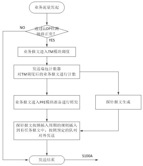

Image

  • Method and system for detecting end-to-end data transmission quality
  • Method and system for detecting end-to-end data transmission quality
  • Method and system for detecting end-to-end data transmission quality

Examples


Embodiment Construction

[0069] In order to better understand the technical content of the present invention, specific embodiments are given and described below in conjunction with the accompanying drawings.

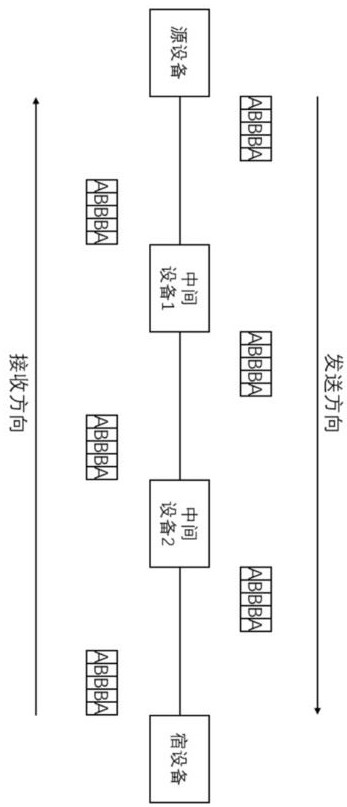
[0070] The method for detecting end-to-end data transmission quality according to an exemplary embodiment of the present invention aims to realize the detection of communication link quality of end-to-end multiple point-to-point links. figure 1 Shown is an application scenario of the link data transmission quality detection method of the present invention.

[0071] The source device and the sink device communicate through multiple point-to-point links. The source device, the sink device, and each intermediate device can be a network element, a server, or any device with a TCP / IP three-layer structure; figure 1 The links in the scenario shown are point-to-point links.

[0072] combine figure 1 , service packets are marked with letter B, and probe packets are marked with letter A. figure 1 Taki...


PUM


Abstract

The invention provides a method and a system for detecting end-to-end data transmission quality. A probe message is added into a communication data stream; three-layer standard packaging is maintainedin packaging; serial numbers are only added to the data fields; any private communication protocol is not needed; generation and statistics of probe messages are realized by newly adding packet insertion, counting and sampling modes at entrances and exits of all devices; and agile monitoring of the service message transmission quality is realized according to the receiving condition of the probemessage. The problem that the packet loss position of the service message cannot be quickly defined according to the current technical means is improved, the quick positioning of the packet loss problem of the end-to-end service message is realized, and the problem that the end-to-end packet loss detection based on the service cannot be quickly and simply deployed in the current data communicationnetwork is solved.

Description

[0001] The present invention relates to the technical field of network communication, in particular to a method and system for detecting end-to-end data transmission quality. Background technique [0002] Network stability is a difficult problem in the field of communication technology, which means that the data of one or more data packets (packets) cannot reach the destination through the Internet. Packet loss may cause jittering in streaming media technology, VoIP, online gaming and video conferencing, and will affect other online applications to a certain extent. There are currently three mainstream packet loss detection methods in the field of data communication technology, namely, transport layer packet loss detection based on TCP retransmission timer, three-layer forwarding scene detection, and application layer segmented deployment ping script detection. [0003] The transport layer packet loss detection method based on the TCP retransmission timer can only detect servi...

Claims


Application Information

Patent Timeline
IPC IPC(8): H04L12/26H04L12/24H04L29/06
CPCH04L41/0677H04L43/0829H04L69/06
Inventor 宗琰陈辉元朱仁军胥晓冬魏荣华张帅
Owner NANJING BESTLINK TECH CO LTD
Learn More